Simulated Inductor
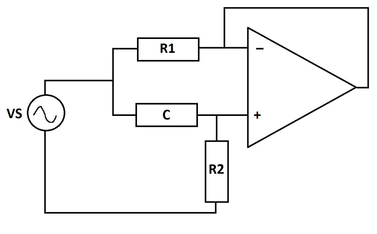
The circuit below is equivalent to connecting a voltage source across a series branch. The circuit consists of resistors, a capacitor, and an ideal operational amplifier with negative feedback. In steady state (after starting transients have died out), what is the peak value of the current flowing out of the source?
Details and Assumptions:
1)
2)
3)
4)
5)
The "golden rules" of op amps apply here
Supplementary Material and Bonus:
1) This youtube video shows the simulated inductor a bit after 4:30. It's worth watching the whole video if you have time. The intro (after the ads) is especially entertaining.
2) Section 4.4 of this tutorial has more details. The equivalent series is evidently just an approximation which holds for certain relative values of the parameters. If you make , the circuit behavior doesn't match the equivalent circuit description.
3) Try simulating the circuit on its own terms to begin with, rather than relying on knowledge of the equivalent circuit
4) Look at the phase angle of the source current with respect to the source voltage. Does it make sense, given the application?

The answer is 0.7071.
This section requires Javascript.
You are seeing this because something didn't load right. We suggest you, (a) try
refreshing the page, (b) enabling javascript if it is disabled on your browser and,
finally, (c)
loading the
non-javascript version of this page
. We're sorry about the hassle.
The currents and voltages at points of interest are indicated in the diagram. The circuit equations have been written assuming that R 2 and the source voltage are connected to the ground. The circuit equations are:
V 1 − V 0 = R 1 I 1 = C Q I 2 = Q ˙ V S = C Q + I 2 R 2 I = I 1 + I 2
Assuming that the capacitor initially has no energy, and rearranging the equations:
V S = C Q + Q ˙ R 2 ⟹ 1 0 − 6 V S = Q + Q ˙ ⟹ 1 0 − 6 sin t = Q + Q ˙ ⟹ 1 0 − 6 e t sin t = e t Q + e t Q ˙ ⟹ d t d ( e t Q ) = 1 0 − 6 e t sin t ⟹ Q = 1 0 − 6 e − t ∫ 0 t e s sin s d s
⟹ Q = 1 0 − 6 e − t ( 2 e t sin ( t ) − e t cos ( t ) + 1 ) Q = 1 0 − 6 ( 2 sin ( t ) − cos ( t ) + e − t )
Now, from the circuit equations:
I = I 1 + I 2 ⟹ I = R 1 C Q + Q ˙
Plugging in expressions:
⟹ I = 2 sin ( t ) − cos ( t ) + e − t + 1 0 − 6 ( 2 sin ( t ) + cos ( t ) − e − t )
Neglecting the term multiplied by 1 0 − 6 gives:
I ≈ 2 sin ( t ) − cos ( t ) + e − t
At steady state:
I ≈ 2 sin ( t ) − cos ( t )
At this point, it is easy to conclude that the peak value of current is approximately:
I m a x ≈ 2 1
As for the bonus question, consider the circuit equations as shown above. Assuming zero initial conditions, the Laplace transform is applied to each of the equations yielding:
V S ( s ) = ( C 1 + s R 2 ) Q ( s ) s Q ( s ) = I 2 ( s ) I ( s ) = I 1 ( s ) + I 2 ( s ) I 1 ( s ) = R 1 C Q ( s )
Solving for I ( s ) gives:
I ( s ) = ( R 1 + s C R 2 R 1 1 + s C R 1 ) V S ( s ) … ( 1 )
Now, for a conventional RL circuit, the circuit equation in the Laplace domain is:
I ( s ) = L s + R V S ( s ) … ( 2 )
For (1) to behave similar to a RL circuit, it must resemble the mathematical structure of (2). This is only possible when the product R 1 C is a small number in magnitude. For the given set of parameters, this is indeed satisfied. For the case when R 1 = R 2 = C = 1 , this condition is not satisfied as the circuit behaves as a purely resistive circuit.
So, one can see that the given circuit is equivalent to an RL circiut provided R 1 C is a small number in magnitude. The magnitude and phase response in the frequency domain will start to resemble that of an RL circuit when this condition is satisfied.