Strange Light Bulb Setup
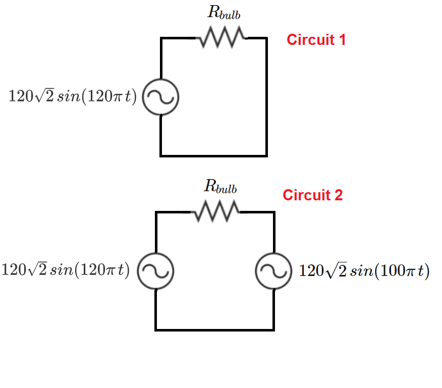
Circuit 1 below represents a standard AC wall outlet voltage applied across a light bulb filament. In Circuit 2, voltage sources at and simultaneously excite the bulb.
If the bulb in Circuit 1 dissipates Joules of energy between to , how many Joules are dissipated in the Circuit 2 bulb over the same time period?
The answer is 80.0.
This section requires Javascript.
You are seeing this because something didn't load right. We suggest you, (a) try
refreshing the page, (b) enabling javascript if it is disabled on your browser and,
finally, (c)
loading the
non-javascript version of this page
. We're sorry about the hassle.
In the first case the dissipation is P = R 2 ( 1 2 0 ) 2 sin 2 ω 1 t , where the time average is sin 2 ω 1 t = 1 / 2 , so P = 1 2 0 2 / R .
In the second case P ′ = R 2 ( 1 2 0 ) 2 ( sin ω 1 t − sin ω 2 t ) 2 . To calculate the average we use a trigonometric identity ( sin ω 1 t − sin ω 2 t ) 2 = sin 2 ω 1 t + sin 2 ω 2 t − 2 sin ω 1 t sin ω 2 t = sin 2 ω 1 t + sin 2 ω 2 t + cos ( ω 1 + ω 2 ) t + cos ( ω 1 − ω 2 ) t . The time averages are
sin 2 ω 1 t = 1 / 2 ,
sin 2 ω 2 t = 1 / 2 ,
cos ( ω 1 + ω 2 ) t = 0 and
cos ( ω 1 − ω 2 ) t = 0 .
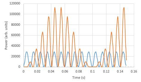
Therefore P ′ = 2 P = 8 0 W . Please note that this argument works accurately if all of the oscillations involve an integer number of periods over the time of 1s. Easy to see that this is the case here. Also note that the the result is independent of the phase angle between the two oscillations, so if we use sin ω 1 t + sin ω 2 t instead of sin ω 1 t − sin ω 2 t , we get the same result. Finally, the power dissipation has a 10Hz oscillation between zero power and four times of the original power - the light bulb is in great danger of burning out. See the graph below.