Swing's the Thing
In the AC circuit below, the switch closes at time t = 0 , and the inductor is de-energized prior to closing. The source voltages are:
V S = 1 0 cos ( ω 1 t ) V R = 1 0 sin ( ω 2 t )
Between t = 0 and t = 3 , how much energy is dissipated in the resistor?
Bonus: To intuitively understand the current envelope, can you make any connection between this and steady-state AC circuit analysis? I also threw a decaying DC offset in there just for fun.
Details and Assumptions:
1)
f
1
=
6
1
Hz
,
ω
1
=
2
π
f
1
rad/s
2)
f
2
=
6
0
Hz
,
ω
2
=
2
π
f
2
rad/s
3)
R
=
0
.
0
0
5
Ω
4)
L
=
ω
2
1
H
![]()
The answer is 1.607.
This section requires Javascript.
You are seeing this because something didn't load right. We suggest you, (a) try
refreshing the page, (b) enabling javascript if it is disabled on your browser and,
finally, (c)
loading the
non-javascript version of this page
. We're sorry about the hassle.
2 solutions
The equation for this circuit is:
− V S + I R + L d t d I + V R = 0
I ( 0 ) = 0
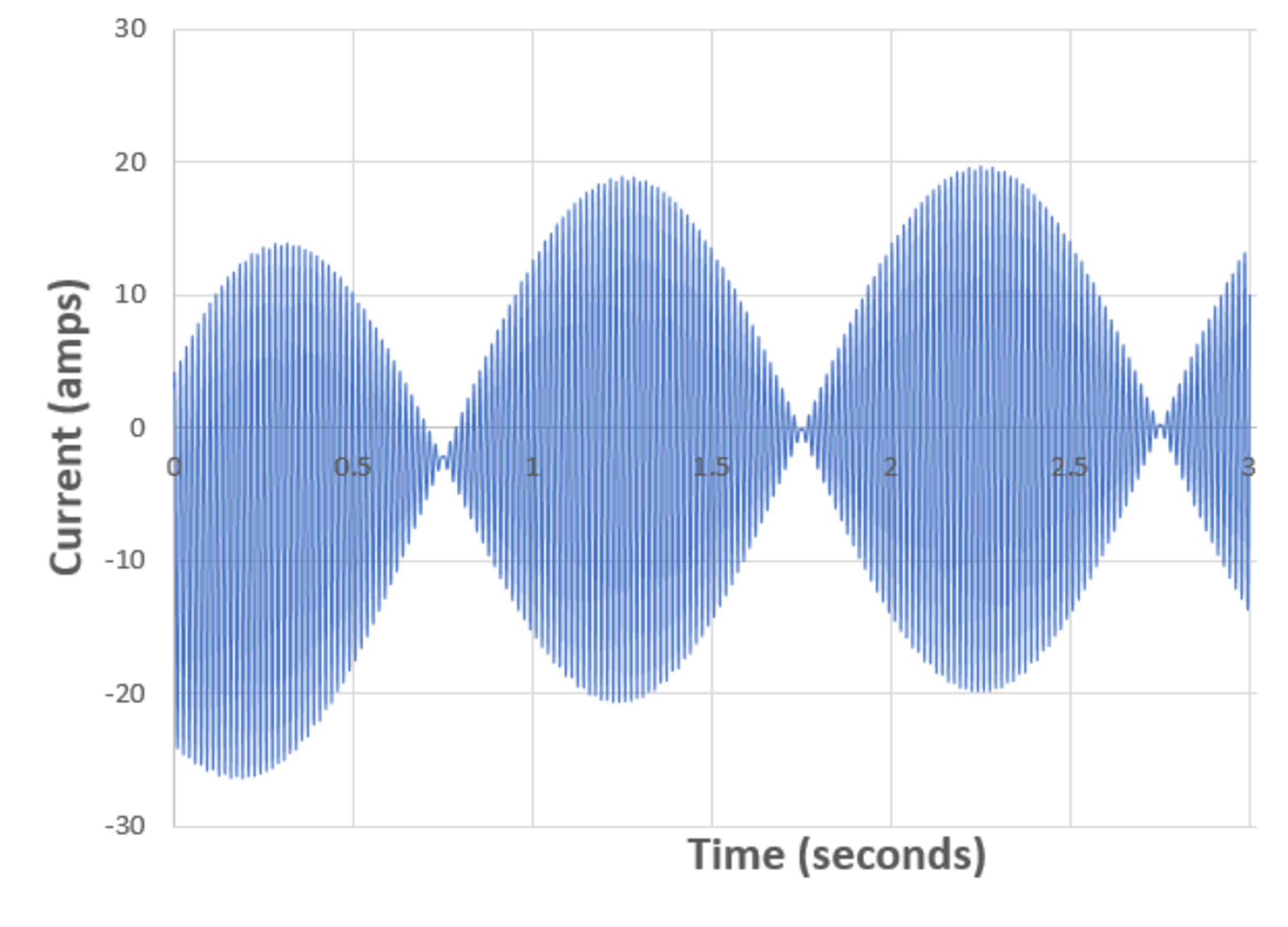
Solving for I as a function of time yields the plot as seen in the problem statement. The goal of this problem is to compute:
E = ∫ 0 3 I ( t ) 2 R d t
The answer comes out to be 1.6069 J .
An analytical solution can be derived but computations are cumbersome. Numerical approaches have been used at each stage.
Coming to the steady-state analysis, first, the source V R is ignored: V S , s s = 1 0 i Z 1 = R + i ω 1 L
I S , s s = Z 1 V S , s s
On ignoring the source V S : V R , s s = − 1 0 Z 2 = R + i ω 2 L
I R , s s = Z 2 V R , s s
On applying the superposition principle:
I = I S , s s + I R , s s
On taking the modulus of the resulting complex number:
∣ I ∣ = 1 4 . 0 2 5 9 A
I am unable to draw a connection between steady-state and transient analysis. The peak current predicted after a steady-state analysis is quite different from the anticipated value of 19.8357 A. Wonder where I'm going wrong here.
To be truly rigorous, one must operate in the time-domain, as @Karan Chatrath has done in his solution. A somewhat less rigorous, but still useful, perspective is the following:
1) To represent the sources in a quasi-AC-steady-state context, think of two vectors in the complex plane.
2) One vector is stationary, and the other is effectively rotating at a rate of 1 Hz , which happens to be the "slip frequency" between the two
3) Over the course of one second, the two vectors have every possible relative phase relationship.
4) When the vectors are perfectly in phase, the AC voltage across the R L branch is zero, yielding the trough in the current envelope
5) When the vectors are perfectly out of phase, the AC voltage across the R L branch is 2 0 , yielding the peak in the current envelope
6) During the AC current peak, we effectively have 2 0 volts across 1 ohm, resulting in 2 0 peak amps of AC current.