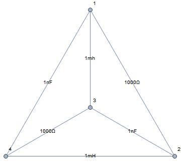
Tetrahedron impedance planar network -- What is the impedance magnitude between nodes 1 & 2?

This is an AC circuit operating at a frequency of . The inductors are 1 mH and the capacitors are 1 nF.
Simplifying assumptions: the components are pure, ideal components, there is no mutual inductance between the inductors and the wiring is negligible.
The device impedance formulae are simple and the frequency was chosen to give integer impedance magnitudes, in the sense that a unit circle in the complex plane has a magnitude of around the entire circle. The standard unit for inductors is a Henry and for capacitors is a Farad. Convert the units used above to those units before computing the device impedances.
Kirchhoff's circuit laws and some matrix algebra (simultaneous equations) work should yield the result. If you did the phase angle version of this problem, then you have no more work to do.
The answer is 500.
This section requires Javascript.
You are seeing this because something didn't load right. We suggest you, (a) try
refreshing the page, (b) enabling javascript if it is disabled on your browser and,
finally, (c)
loading the
non-javascript version of this page
. We're sorry about the hassle.
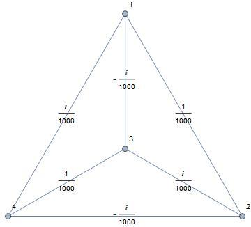
With the impedances entered as conductances, the graph is:
The computation method: resistance = With [ { Γ = PseudoInverse [ With [ { wam = WeightedAdjacencyMatrix [ $#$1 ] } , DiagonalMatrix [ Tr /@ wam T ] − wam ] ] } , Outer [ Plus , Diagonal [ Γ ] , Diagonal [ Γ ] ] − Γ − Γ T ] & ; .
The result: ⎝ ⎜ ⎜ ⎛ 0 5 0 0 2 5 0 + 2 5 0 i 2 5 0 − 2 5 0 i 5 0 0 0 2 5 0 − 2 5 0 i 2 5 0 + 2 5 0 i 2 5 0 + 2 5 0 i 2 5 0 − 2 5 0 i 0 5 0 0 2 5 0 − 2 5 0 i 2 5 0 + 2 5 0 i 5 0 0 0 ⎠ ⎟ ⎟ ⎞ .
The impedance between nodes 1 and 2, the 500 in the second entry of the first row is the answer. The circuit between nodes 1 and 2 is pure resistive.