Thermal Expansion Joint
Most materials expand when their temperature increases. Because the expansion depends on the dimensions of the object, long runs of pipe can often undergo expansion of several inches, which can cause problems if not properly accounted for.
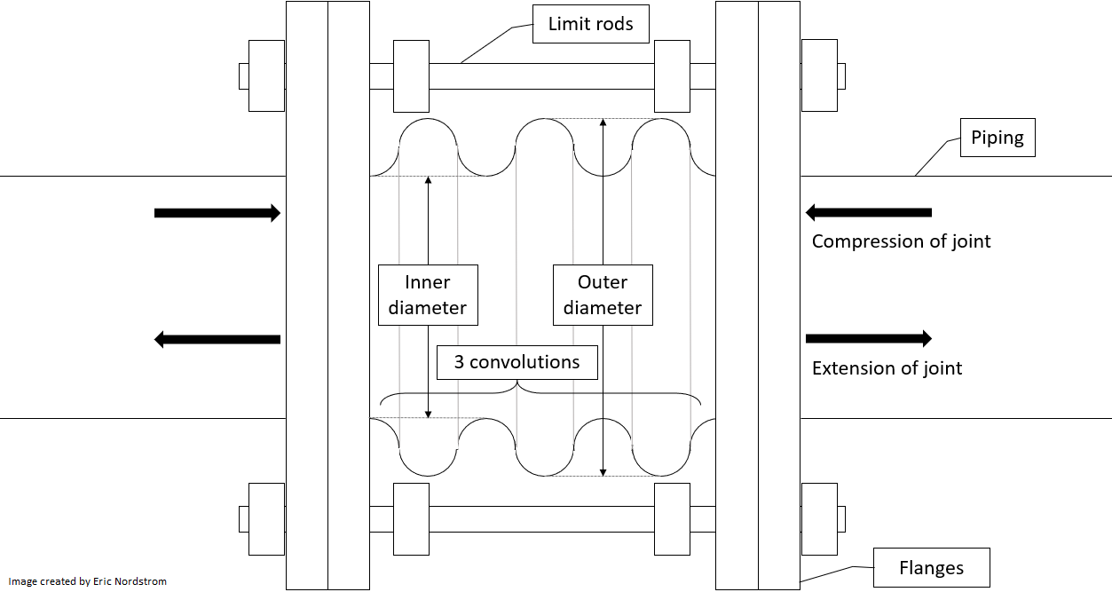
A common way to solve this problem is by installing an expansion joint in the pipe to absorb the expansion. The flexible element of a bellows expansion joint consists of corrugated sheet metal or elastomer with any number of repetitions of changing radius called convolutions . A diagram of an axial bellows expansion joint , the motion of which is only in the axial direction, is shown below.

There are two components that make up the force a bellows joint exerts on pipes:
- the spring-like force caused by offset from the equilibrium position and
- the pressure thrust caused by pressurized fluid pushing outward from inside the bellows.
Consider the axial bellows expansion joint below, which is in a 200-foot section of carbon steel pipe held between two fixed points ( anchors ). The joint has 5 convolutions, an inner diameter of 4 inches, and an outer diameter of 5 inches. The piping is part of a heating hot water (HHW) system, which pumps 180 F water through HVAC units on cold days. When the piping components (pipes, guides, anchors, expansion joints, etc.) were installed but the system had not yet been filled with water, the pipes were not exerting any horizontal force on the anchors, and the ambient temperature was 50 F.

The HHW system has been running continuously for a long time, but at present the pumps have just been turned off, and the water has come to rest with a pressure of 80 psi above atmospheric in the illustrated section of piping. How many pounds of force do the pipes exert on the anchors, to the nearest pound, assuming the following?
- The length of the expansion joint is negligible compared to the length of the pipes.
- The sidewalls (annular faces) of the convolutions remain approximately vertical throughout any extension or compression.
- The spring rate , which is analogous to the spring coefficient in a spring, is 300 lbs/in.
- The effective area to which fluid pressure is applied to generate pressure thrust is a circle whose diameter is the mean of the inner and outer diameters of the bellows.
- There is not much heat transfer between the pipes and the surrounding air during operation.
- The pipes expand according to this table .
The answer is 1872.
This section requires Javascript.
You are seeing this because something didn't load right. We suggest you, (a) try
refreshing the page, (b) enabling javascript if it is disabled on your browser and,
finally, (c)
loading the
non-javascript version of this page
. We're sorry about the hassle.
This problem is mostly about reading and understanding what is happening in the problem and was hopefully not too difficult otherwise. Some of the information was unnecessary, such as the number of convolutions and the extra details about limit rods, etc.
We know the pipes experienced--and therefore exerted (Newton's third law)--zero net force after they were installed because they were not accelerating in any direction. To sum the forces to zero, the pipes could not have been exerting any force on the expansion joint since they were also not exerting any load on the anchors. Therefore, the expansion joint was at its equilibrium position at this initial time. All the force on the anchors will be due to expansion and pressure thrust.
According to the table, for a temperature change of 50 to 180 ∘ F, carbon steel pipe expands 1 . 4 − 0 . 4 = 1 . 0 inch per 100 ft. For the 200 ft run, this means 2 inches of pipe expansion . The anchors are fixed points, so the pipes expand inward toward the expansion joint, and this translates to 2 inches of compression of the joint. We know the pipe will reach this temperature because there is not much heat transfer with the surrounding air, so the pipe temperature will equal the temperature of the hot water during operation. The initial temperature is best assumed to be the same as the ambient temperature.
The first component of the force is the elastic force in response to the compression, which, based on the analogy to a spring, is spring rate × distance from equilibrium = 3 0 0 in. lbs × 2 in. = 6 0 0 lbs .
The second component is the pressure thrust. One might be tempted to look at the shape of the bellows, try to calculate force for each convolution, and determine which force cancel out or add up. However, it was given that the effective area to generate pressure thrust is simply a circle of diameter 2 I.D. + O.D. = 4 . 5 in. The area is therefore A = 4 π ( 4 . 5 ) 2 = 1 5 . 9 0 4 sq. in. The force resulting from a pressure is P A , so we just have to multiply the area by the pressure. However, there is also an opposing force from the surrounding air, which can be assumed at atmospheric pressure. Once this is accounted for, the pressure thrust can be calculated using only the gauge pressure (pressure relative to atmospheric). This is P gauge A = ( 8 0 ) ( 1 5 . 9 0 4 ) = 1 2 7 2 lbs .
In total, the force exerted by the expansion loop on the pipes is 6 0 0 + 1 2 7 2 = 1 8 7 2 lbs . This is the force that is transmitted to the anchors through the pipes, which the anchors must be selected to withstand.