This section requires Javascript.
You are seeing this because something didn't load right. We suggest you, (a) try
refreshing the page, (b) enabling javascript if it is disabled on your browser and,
finally, (c)
loading the
non-javascript version of this page
. We're sorry about the hassle.
2 solutions
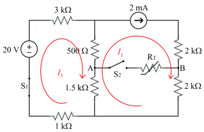
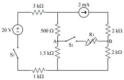
By mesh analysis :
I 1 − 2 0 + 3 I 3 + ( 0 . 5 + 1 . 5 ) ( I 3 − I 1 ) + 1 I 3 − 2 0 + 3 I 3 + 2 ( I 3 − 2 ) + I 3 6 I 3 ⟹ I 3 = 2 = 0 = 0 = 2 4 = 4 m A . . . ( 1 )
Therefore, V A B = 1 . 5 ( I 3 − I 1 ) − 2 I 1 = 1 . 5 ( 4 − 2 ) − 2 ( 2 ) = − 1 V .
Label node voltages V 1 and V 2 as shown in the modified diagram. For each of these nodes, the sum of the currents flowing out must equal zero.
R 5 V 1 − V S + R 1 + R 2 V 1 − V 2 + I S = 0 R 6 V 2 + R 1 + R 2 V 2 − V 1 − I S = 0
Solve for V 1 and V 2 . The current through R 1 and R 2 is:
I = R 1 + R 2 V 1 − V 2
The voltage at A is:
V A = V 1 − R 1 I
The voltage at B is:
V B = V 2 + R 4 I S
Numerical results:
V 1 = 8 V 2 = 4 V A = 7 V B = 8 V A B = − 1