This section requires Javascript.
You are seeing this because something didn't load right. We suggest you, (a) try
refreshing the page, (b) enabling javascript if it is disabled on your browser and,
finally, (c)
loading the
non-javascript version of this page
. We're sorry about the hassle.
3 solutions

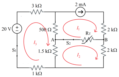
To provide varieties, I am using mesh analysis .
I 1 1 . 8 7 5 ( I 2 − I 1 ) + 2 I 2 + 1 . 5 ( I 2 − I 3 ) 5 . 3 7 5 I 2 − 1 . 5 I 3 − 2 0 + 3 I 3 + 0 . 5 ( I 3 − I 1 ) + 1 . 5 ( I 3 − I 2 ) + 1 I 3 − 1 . 5 I 2 + 6 I 3 = 2 = 0 = 3 . 7 5 = 0 = 2 1 . . . ( 1 ) ( 1 ) : I 1 = 2 . . . ( 2 ) . . . ( 3 )
( 3 ) + 4 × ( 2 ) : 2 0 I 2 ⟹ I 2 = 3 6 = 1 . 8 m A
Therefore the power dissipated by the thermistor at 2 5 ∘ C , P = ( I 1 − I 2 ) 2 R T = ( 2 − 1 . 8 ) 2 × 1 0 − 6 × 1 8 7 5 = 7 5 × 1 0 − 6 = 7 5 μ W .
From part 2 , it was calculated that when switch 1 is closed but switch 2 is open, the voltage difference between nodes A and B is V A − V B = − 1 V . This is equivalent to the Thevenin voltage of the circuit, where the load is the thermistor. This means that the Thevenin voltage V T H = 1 V , taking the absolute value since the sign doesn't really matter. (The voltage and current will have the same sign in P = I V )
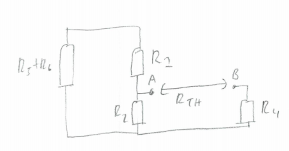
Now to calculate the Thevenin resistance
R
T
H
, set all sources to zero, while removing the load.
 R
1
,
R
5
and
R
6
are all in series, and the equivalent resistance of these 3 resistors is in parallel with
R
2
. The Thevenin resistance is therefore:
R
T
H
=
R
2
+
R
1
+
R
5
+
R
6
R
2
(
R
1
+
R
5
+
R
6
)
+
R
4
=
1
.
5
+
0
.
5
+
3
+
1
1
.
5
(
0
.
5
+
3
+
1
)
+
2
=
6
1
.
5
×
4
.
5
+
2
=
3
.
1
2
5
k
Ω
R
1
,
R
5
and
R
6
are all in series, and the equivalent resistance of these 3 resistors is in parallel with
R
2
. The Thevenin resistance is therefore:
R
T
H
=
R
2
+
R
1
+
R
5
+
R
6
R
2
(
R
1
+
R
5
+
R
6
)
+
R
4
=
1
.
5
+
0
.
5
+
3
+
1
1
.
5
(
0
.
5
+
3
+
1
)
+
2
=
6
1
.
5
×
4
.
5
+
2
=
3
.
1
2
5
k
Ω
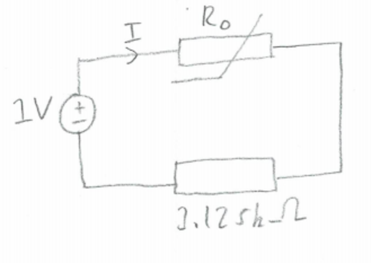
 Thevenin's equivalent circuit
I
=
1
.
8
7
5
+
3
.
1
2
5
1
=
5
1
=
0
.
2
mA
Power dissipated by the thermistor:
P
=
I
2
R
0
=
(
0
.
2
mA
)
2
×
1
.
8
7
5
k
Ω
=
0
.
0
7
5
mW
=
7
5
μ
W

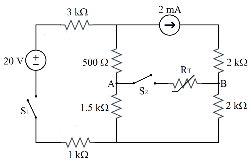
There are four unknown node voltages, as shown in the modified diagram. For each node, the sum of the currents flowing outward is zero. The equations are (assume that the non-polarity side of the voltage source is the reference voltage):
R 5 V 1 − V S + R 1 V 1 − V A + I S = 0 R 1 V A − V 1 + R 0 V A − V B + R 2 V A − V 2 = 0 − I S + R 0 V B − V A + R 4 V B − V 2 = 0 R 6 V 2 + R 2 V 2 − V A + R 4 V 2 − V B = 0
Solve the linear system for these four voltages. The voltage across the thermistor is:
V A B = V A − V B
The power dissipated by the thermistor is:
P = R 0 V A B 2
Numerical results:
V 1 = 8 . 1 5 V 2 = 3 . 9 5 V A = 7 . 1 7 5 V B = 7 . 5 5 P = 7 5 μ W