Three-Phase Transient
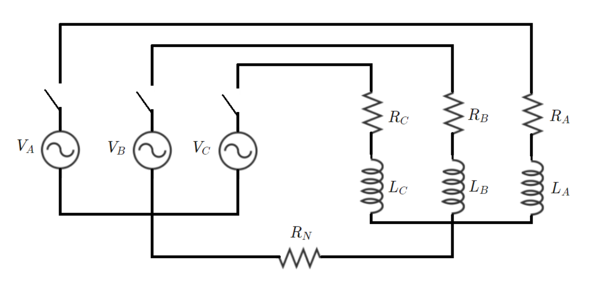
The three AC voltage waveforms are as follows:
V A = 1 0 0 sin ( ω t ) V B = 1 0 0 sin ( ω t − 2 π / 3 ) V C = V C M sin ( ω t + V C A ) V C M = 1 1 1 . 7 3 9 2 4 2 0 1 7 V C A = 1 . 9 6 2 8 2 4 5 5 2 9 3
At time t = 0 , the three switches close simultaneously. Prior to switch closing, all of the inductors are de-energized.
How much energy is dissipated in the neutral resistor R N between t = 0 and t = 1 0 ?
Note: Ideally, the neutral current would be zero in steady state, but there are some small imperfections in the values I have given for the C-phase voltage. That is why I have restricted the integration range.
Details and assumptions:
1)
R
A
=
1
Ω
,
R
B
=
2
Ω
,
R
C
=
3
Ω
,
R
N
=
1
Ω
2)
L
A
=
L
B
=
L
C
=
ω
1
0
H
3)
ω
=
1
2
0
π
rad/s
The answer is 0.0685.
This section requires Javascript.
You are seeing this because something didn't load right. We suggest you, (a) try
refreshing the page, (b) enabling javascript if it is disabled on your browser and,
finally, (c)
loading the
non-javascript version of this page
. We're sorry about the hassle.
1 solution
Greetings. I used explicit Euler with time steps of 1 0 − 5 and 1 0 − 6 . There is indeed a small sinusoidal current which persists. I'm guessing this is because I was only able to provide finitely many decimal places for the c-phase voltage parameters. I have modified the problem to restrict the integration window to 0 ≤ t ≤ 1 0 . Even when I integrate out to t = 1 0 0 , I get a negligible error, relative to the desired answer. But it is true that integrating out far enough would cause a problem.
Let the current flowing through R A be i 1 , R B be i 2 , and R C be i 3 . Using Kirchoff's voltage and current laws, the equations for the circuit can be written as follows. Note that the current through R N is I = I 1 + I 2 + I 3 .
− V A + I 1 R A + L d t d I 1 + ( I 1 + I 2 + I 3 ) R N = 0 − V B + I 2 R B + L d t d I 2 + ( I 1 + I 2 + I 3 ) R N = 0 − V C + I 3 R C + L d t d I 3 + ( I 1 + I 2 + I 3 ) R N = 0
The above system of differential equations can be recast into a state-space form as such:
⎣ ⎡ I ˙ 1 I ˙ 2 I ˙ 3 ⎦ ⎤ = ⎣ ⎡ L R A + R N L R N L R N L R N L R B + R N L R N L R N L R N L R C + R N ⎦ ⎤ ⎣ ⎡ I 1 I 2 I 3 ⎦ ⎤ + ⎣ ⎡ L 1 0 0 0 L 1 0 0 0 L 1 ⎦ ⎤ ⎣ ⎡ V A V B V C ⎦ ⎤ I = [ 1 1 1 ] ⎣ ⎡ I 1 I 2 I 3 ⎦ ⎤
Using a more convenient shorthand notation, one can write the above equations as:
x ˙ = A x + B u I = C x
At time t = 0 , there is no current flow in the circuit. Using this fact as initial conditions, the system of differential equations was solved using simulation software and the current I was obtained. The following quantity is required to be computed.
E = ∫ 0 ∞ I 2 R N d t
The answer comes out to be 0 . 0 6 8 5 J .
The numerical aspects of this problem proved to be interesting. I initially used the integration method of RK-4 with a step size of 0.001 s. It was observed that the current I does not converge to zero. To obtain a finite value of energy dissipated, the current must converge to zero after a finite time. I then used a higher-order accurate fixed-step integration technique to observe convergence. I will add a couple of plots to this solution a little later and explain my work in some detail. However, I was curious. I have studied your past solutions to problems, and have observed that you use the Euler step to numerically integrate. Did that method work accurately here? What was your simulation time step?