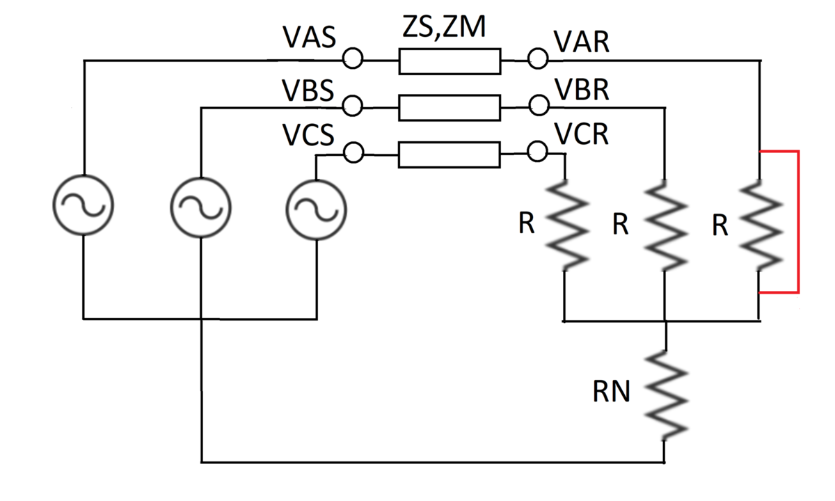
Transmission Line with Load Fault
A balanced three-phase voltage source feeds a set of load resistors through a transmission line. The three phases of the transmission line are magnetically coupled, which can be modeled using self and mutual impedances as follows:
V A S − Z S I A − Z M I B − Z M I C = V A R V B S − Z M I A − Z S I B − Z M I C = V B R V C S − Z M I A − Z M I B − Z S I C = V C R
In the circuit, the star (neutral) point of the voltage sources is taken as the voltage reference. By convention, the currents flow across the transmission line from left to right. The system parameters are:
V A S = 1 0 0 e j 0 V B S = 1 0 0 e − j 2 π / 3 V C S = 1 0 0 e j 2 π / 3 Z S = 1 + j 1 0 Z M = 1 + j 5 R = 1 0 R N = 2
There is a fault which short-circuits the phase A load resistor (as shown in red in the diagram).
What is the magnitude of voltage V C R ?
Bonus: Is this result intuitive?
The answer is 111.22.
This section requires Javascript.
You are seeing this because something didn't load right. We suggest you, (a) try
refreshing the page, (b) enabling javascript if it is disabled on your browser and,
finally, (c)
loading the
non-javascript version of this page
. We're sorry about the hassle.
1 solution
As for the bonus question, I would say it is counter-intuitive. I expected the voltage magnitude V C R to be lower than V C S .
Log in to reply
Indeed, the mutual coupling can yield some surprising results. Thanks for the solution
The first step is writing down the circuit equations by applying Kirchoff's laws.
V A S = ( V A S − V A R ) + ( I A + I B + I C ) R N V B S = ( V B S − V B R ) + I B R + ( I A + I B + I C ) R N V C S = ( V C S − V C R ) + I C R + ( I A + I B + I C ) R N
Replacing the equation V A S − V A R by the given transmission line model, in each equation, re-writing and simplifying gives:
⎣ ⎡ V A S V B S V C S ⎦ ⎤ = ⎣ ⎡ D − R N N N D N N N D ⎦ ⎤ ⎣ ⎡ I A I B I C ⎦ ⎤ ⟹ V = Z I
Where:
N = Z M + R N D = Z S + R N + R
Let, Z be referred to as an 'impedance matrix'. From here, the currents can be computed by:
I = Z − 1 V
Having computed the currents I A , I B and I C , the final step is the computation of V C R which is as follows:
V C R = V C S − Z M I A − Z M I B − Z S I C
∣ V C R ∣ ≈ 1 1 1 . 2 2 0 1
The above computations are done using a computer to save time. Also, voltage magnitude is computed relative to a point. I assumed that the circuit after R N and before the sources is grounded ( 0 V ).