Two Inductors
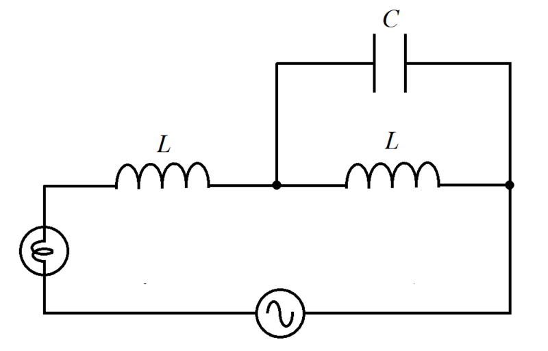
As shown in the figure, an inductor of inductance L is connect to a capacitor of capacitance C parallel with another inductor of inductance L , an incandescent lamp, and a variable frequency alternating voltage source.
It is observed that the lamp is dimmest at an angular frequency ω and brightest at an angular frequency α ω ( α = 0 ). Find α .
The answer is 1.414.
This section requires Javascript.
You are seeing this because something didn't load right. We suggest you, (a) try
refreshing the page, (b) enabling javascript if it is disabled on your browser and,
finally, (c)
loading the
non-javascript version of this page
. We're sorry about the hassle.
2 solutions
@Steven Chase Sir thanks for graph and solution. :)
@Steven Chase can you help me in one question?
@Steven Chase You can post a note
@steven chase sir can you please help me in this problem
Thanks in advance. Hope I am not disturbing you.
Assume that the lamp is purely resistive and has resistance R , which remains constant with temperature. The brightness of the lamp is then proportional to the power it dissipates. Since the lamp's resistance is constant, power is proportional to ∣ I ∣ 2 or square of the amplitude of current passing through the lamp. Since this current I is also the current through the circuit, then we have ∣ I ∣ = ∣ Z ∣ ∣ V ∣ where V is the voltage of the variable frequency voltage source and Z is the resultant impedance of the circuit. Then the brightness of the lamp is proportional to:
∣ I ∣ 2 = ∣ Z ∣ 2 ∣ V ∣ 2 = ∣ ∣ ∣ R + j ω L + j ω C 1 ∣ ∣ j ω L ∣ ∣ ∣ 2 ∣ V ∣ 2 = ∣ ∣ ∣ R + j ω L + j ω C + j ω L 1 1 ∣ ∣ ∣ 2 ∣ V ∣ 2 = ∣ ∣ R + j ( ω L + 1 − ω 2 L C ω L ) ∣ ∣ 2 ∣ V ∣ 2 = R 2 + ( ω L + 1 − ω 2 L C ω L ) 2 ∣ V ∣ 2
We note that ∣ I ∣ 2 is minimum, that is the lamp is dimmest, when ∣ X ∣ = ω L + 1 − ω 2 L C ω L is maximum. That is when 1 − ω 2 L C = 0 , then ∣ X ∣ → ∞ , or ω = L C 1 . And ∣ I ∣ 2 is maximum or the lamp is brightest, when ∣ X ∣ is minimum or ∣ X ∣ = 0 for ω = 0 (not DC), ⟹ ω 1 L + 1 − ω 1 2 L C ω 1 L = 0 or 1 − ω 1 2 L C = − 1 ⟹ ω 1 2 L C = 2 ⟹ ω 1 = L C 2 = 2 ω . Therefore α = 2 ≈ 1 . 4 1 .
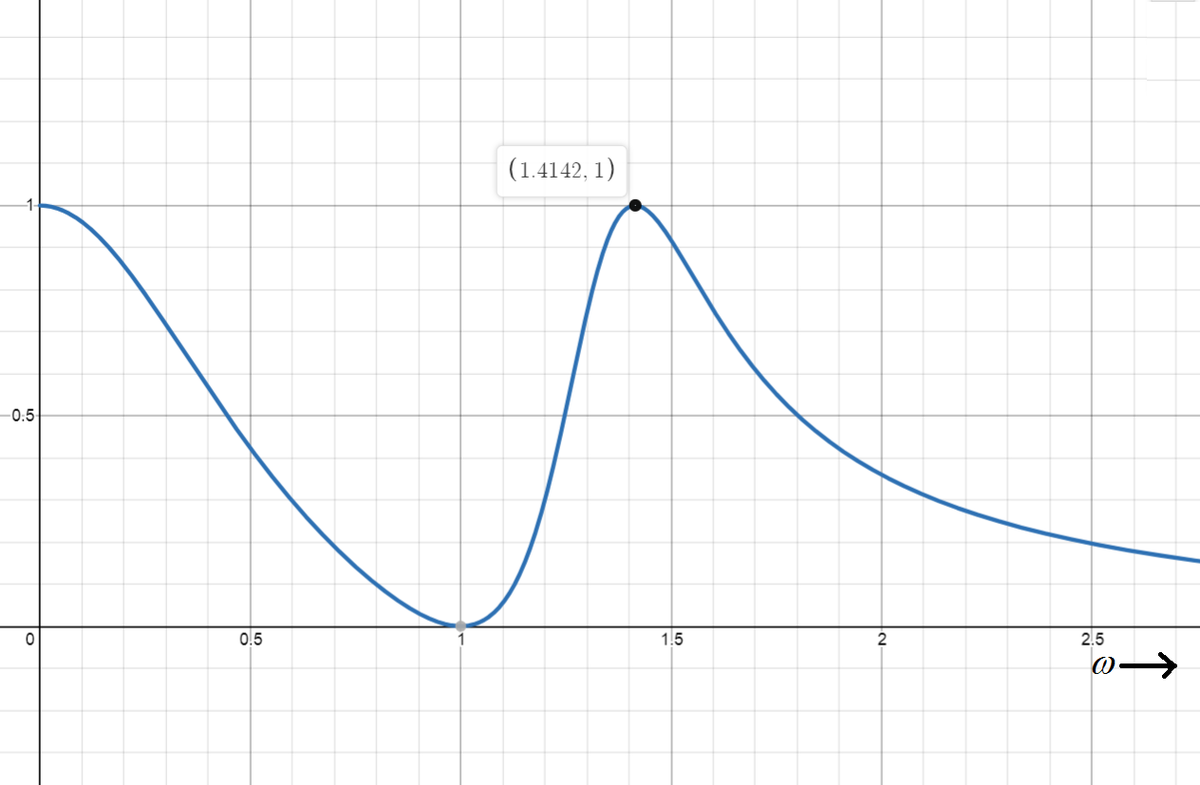
The following is a plot of ∣ I ( ω ) ∣ 2 against ω for ∣ V ∣ = R = C = L = 1 in value. Note that ω = L C 1 = 1 and ω 1 = 2 .
Let ω be the general symbol for the angular frequency. The impedance of the parallel L C branch is:
Z p = j ω L + 1 / j ω C j ω L ( 1 / j ω C ) = 1 − ω 2 L C j ω L
For minimum lamp power, we want the parallel branch impedance to be infinite:
1 − ω 2 L C = 0 ω = L C 1
For maximum power, we want the total circuit impedance to be resistive (just the lamp). This means that the parallel branch must resonate with the other series inductor.
1 − ω 2 L C j ω L = − j ω L 1 − ω 2 L C = − 1 ω = L C 2
Interestingly, there is also another frequency at which this happens. At ω = 0 (DC), the two inductors act as short circuits, and the circuit impedance consists solely of the lamp impedance.
The graph below is a plot of lamp power vs. source angular frequency, for some randomly chosen circuit parameter values.