Amplitude Modulation
The amplitude of the alternating voltage and alternating current in an electronic circuit is often a periodic function dependent on time. It is most common to use sinusoidal functions for this purpose. If, for simplicity, we only consider the case with sinusoidal functions and exclude functions such as square or triangle waves, then the function is said to represent a time dependent wave and thus can be modeled using the time dependent wave equation.
- is the instantaneous amplitude
- is the maximum amplitude
- is the frequency
- is the phase angle
To further simplify the mathematics involved in amplitude modulation I will set the phase angle to zero and ignore it for the rest of this note. The reduced wave equation is as follows:
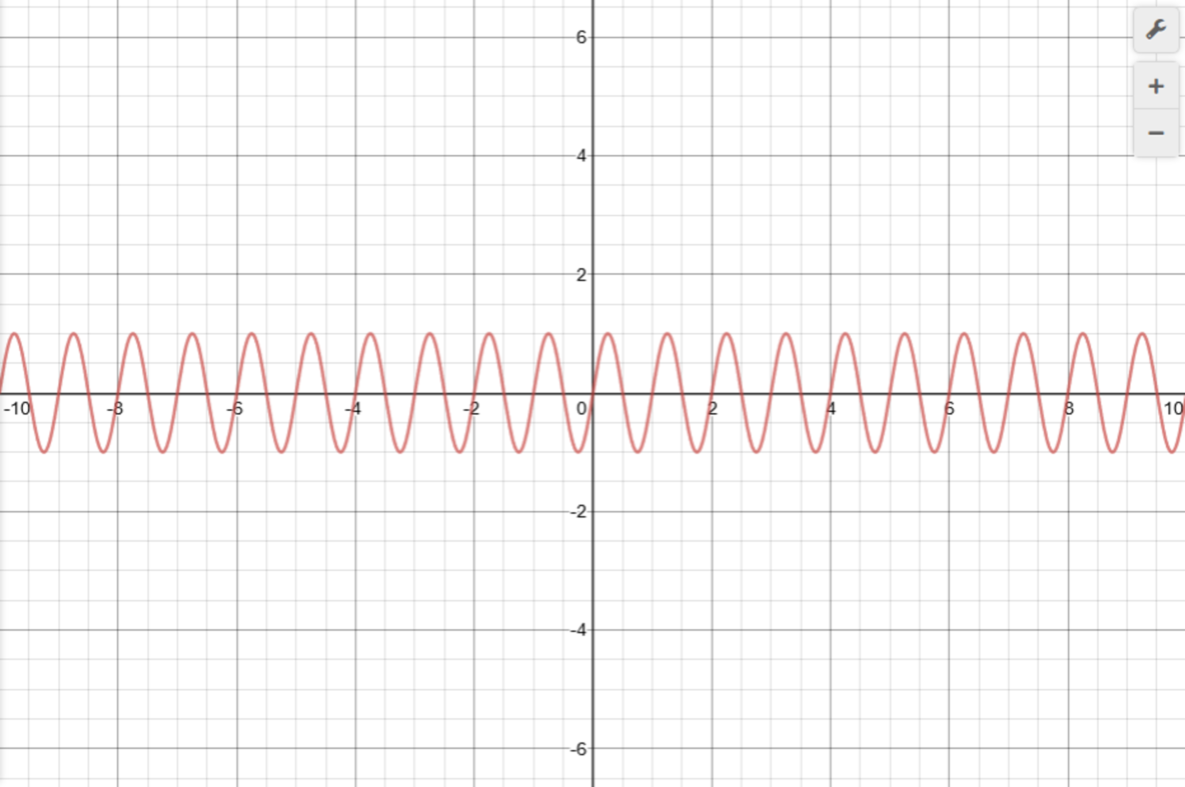
In amplitude modulation the maximum amplitude will itself be an instantaneous value and also a periodic function. The maximum amplitude will increase and decrease by a percentage of a percentage. Using the sinusoidal function again becomes appropriate since percentages are from 0-1 and the sine function returns a value from 0-1.
- is the instantaneous maximum amplitude of the amplitude modulated wave
- is the amplitude of the carrier wave
- is the frequency of the carrier wave
- is the modulation frequency
- is the degree of modulation and is also a percentage ()
The result of substituting the instantaneous value for into our original wave equation is the instantaneous amplitude of the amplitude modulated wave.
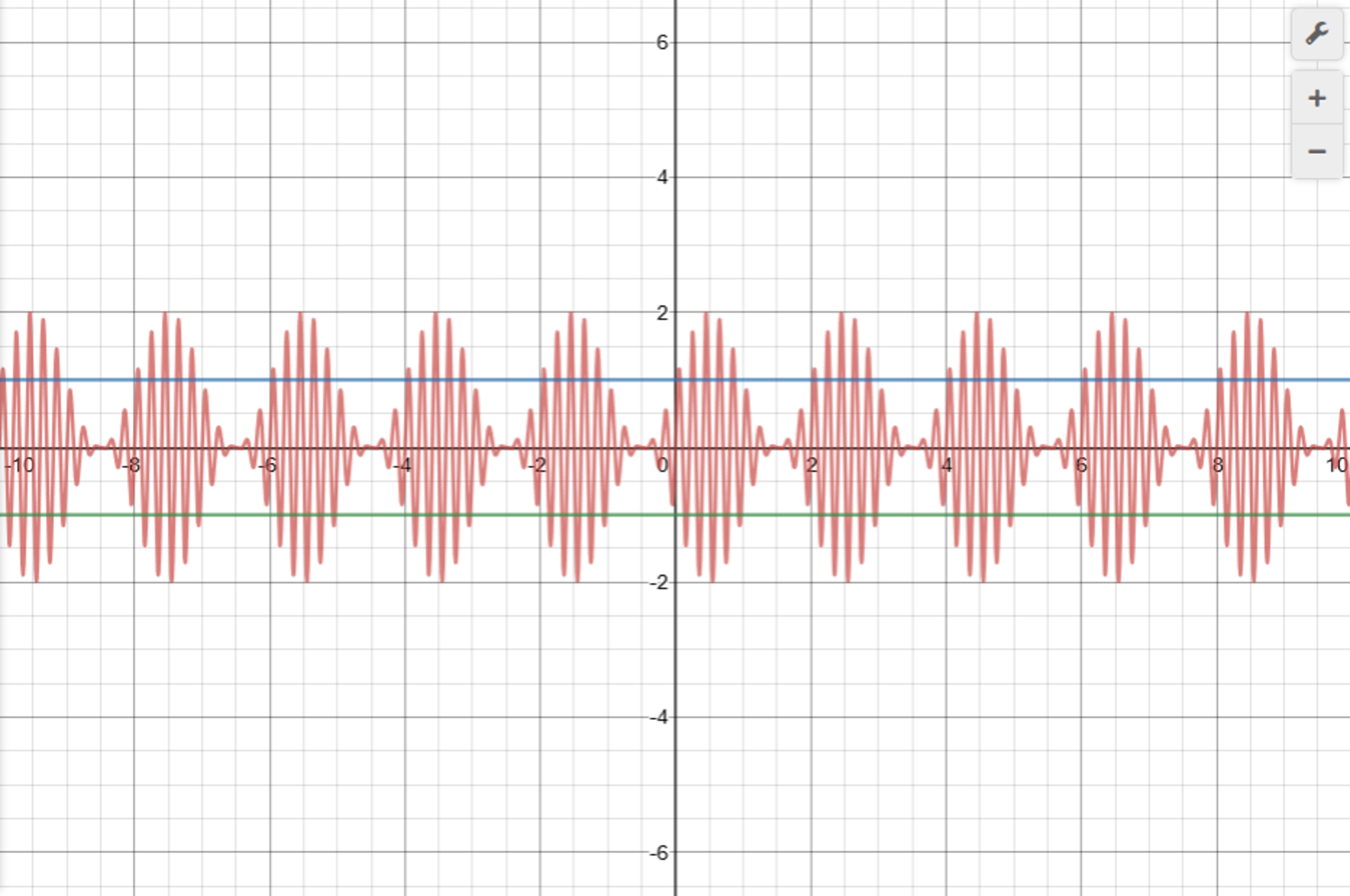
If the degree of modulation, , is equal to zero this equation will reduce to the equation of the carrier wave. If the degree, , is equal to one hundred percent the maximum value of the instantaneous amplitude will be double the carrier wave's amplitude. Now the next thing to do is to expand this equation by using the trigonometric identity for products of two sine functions that says . This is shown as follows.
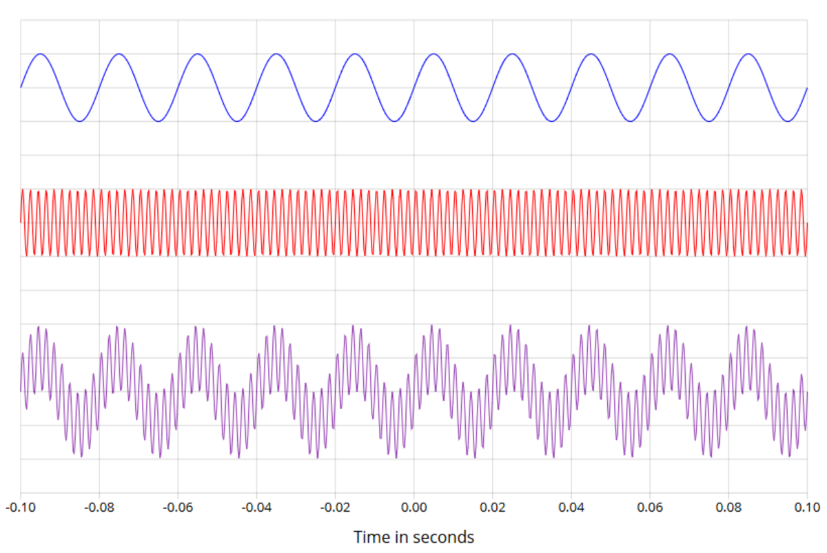
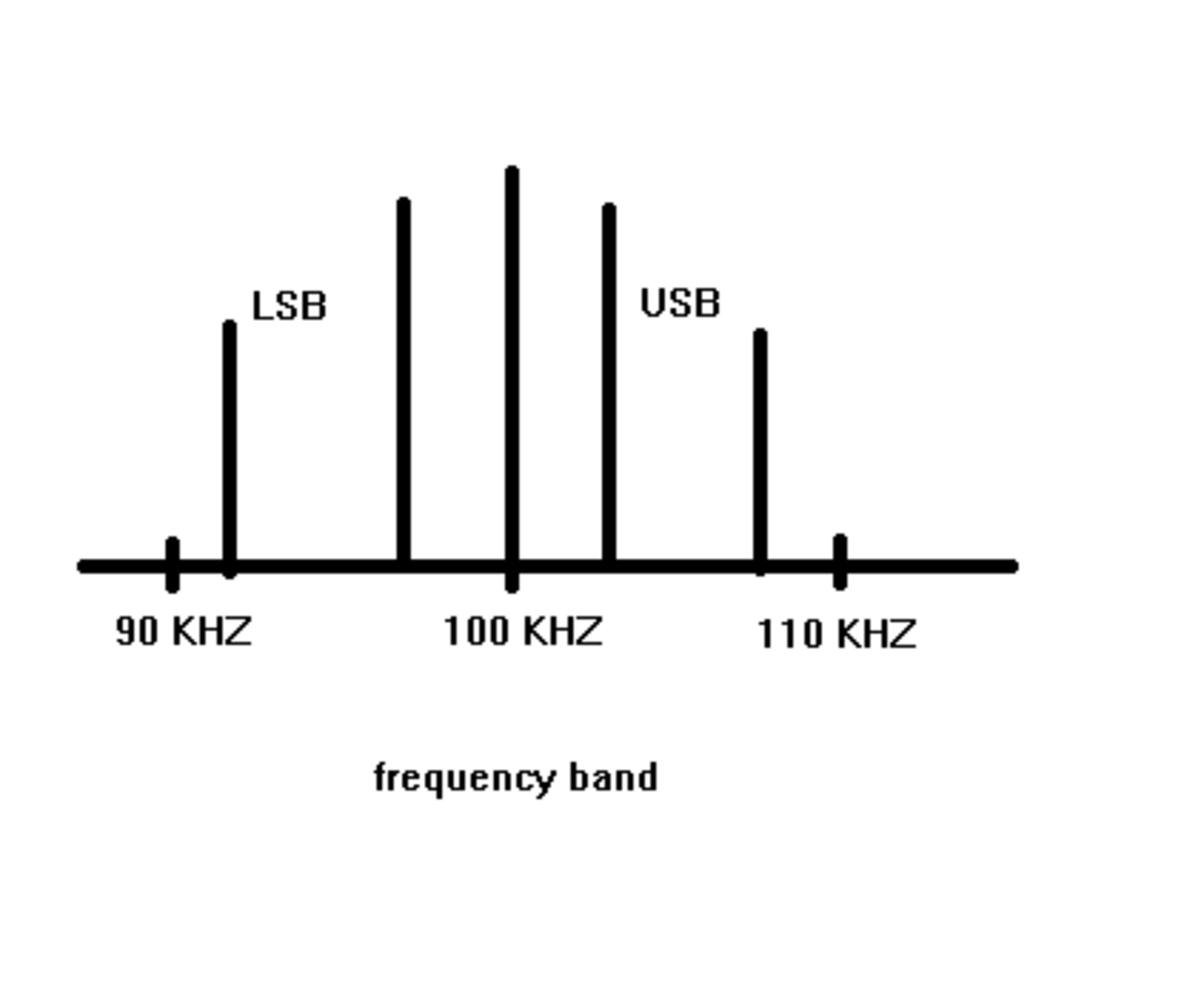
Given the new form of the equation it becomes apparent that the amplitude modulated wave is not actually one wave. It is the superposition of three separate waves operating on three different frequencies. The first term is simply the carrier wave. The other two terms are the side band terms. Thus the amplitude modulated wave is not transmitted at a single frequency but rather across a frequency band. Below is an example of two waves with different frequencies superimposed to give you an idea of what this looks like.
Now that we know what an amplitude modulated wave is and how it is modeled we can start looking at how we can use it for practical purposes. This equation has many variables and therefore it is very important that we understand the effect of each individual variable and then we can decide which values are practical and which are impractical. Some of the things that we will look at in this section are the carrier amplitude, the carrier frequency, the degree of modulation, and the modulation frequency. All of these values will effect the operation of an electrical device.
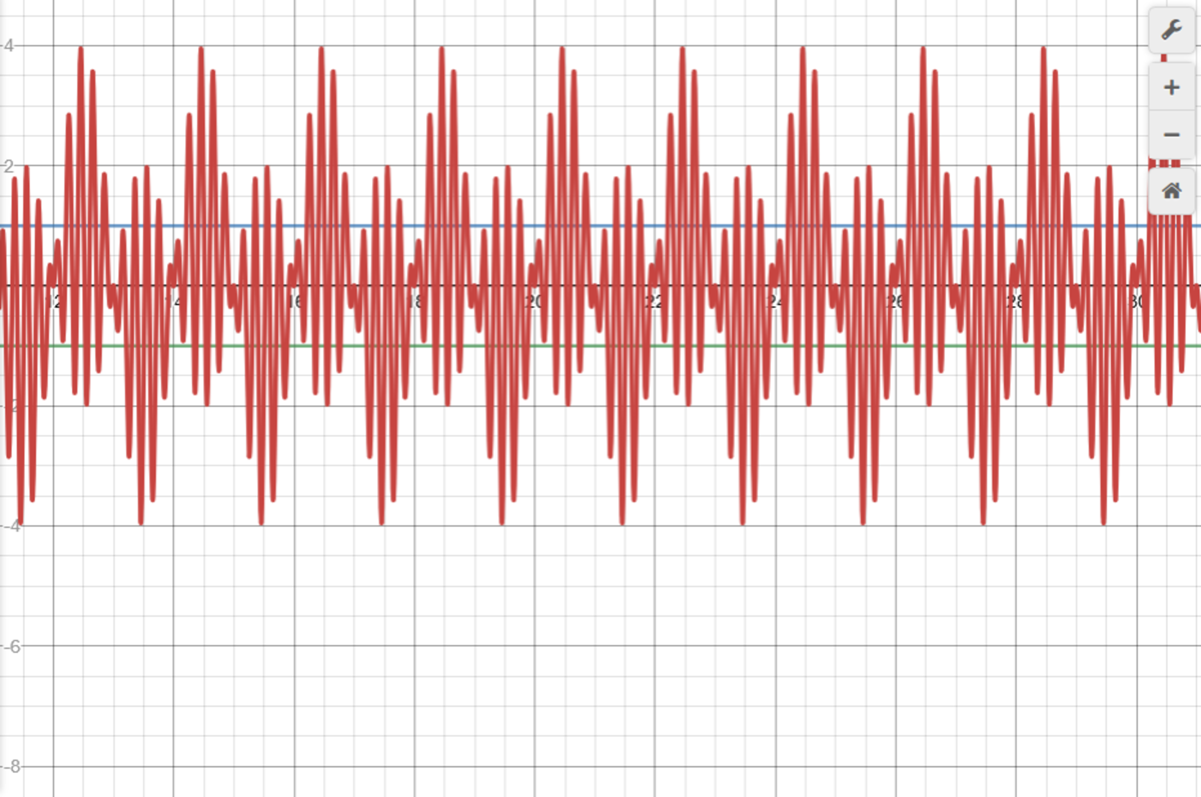
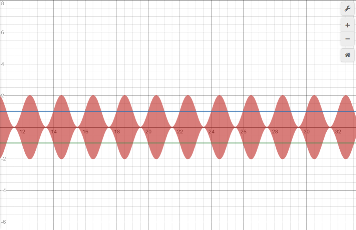
One of the first considerations we will make is to decide what values we should use for the degree of modulation. I said earlier that the degree of modulation should be a number from 0-1 representing 0% -100% which will determine the maximum amplification/ attenuation factor for the carrier wave. If the degree of modulation is larger than one the wave is said to have been over modulated and will result in a distorted waveform from which the signal can not be recovered. The side bands are the part that carries the information of the amplitude modulated wave so we want to make sure the side band has a maximum amount of power and this can be best achieved when the degree of modulation is set to 100%. If you want to ensure the best chances of sending information on an amplitude modulated wave you should use a degree of modulation of 100%. Below is an image to show what a wave with a modulation factor of 300% would look like.
The next consideration to make is what value we should set the modulation frequency to. First we will explore the interesting case where the modulation frequency is set to the same value as the carrier wave frequency and see what happens.

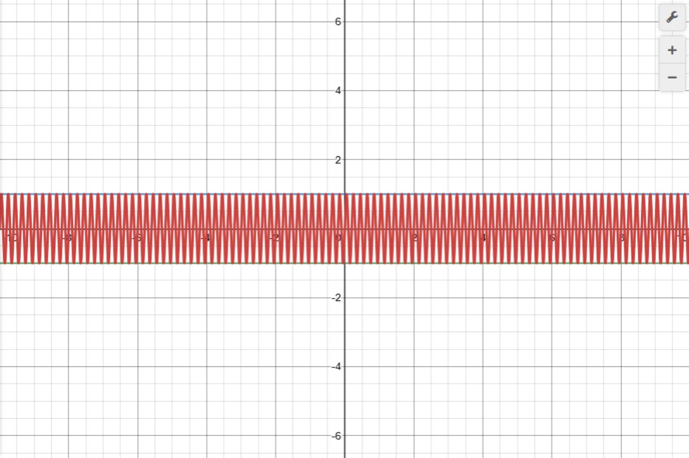
The result is a special case of the amplitude modulated wave since one of the side band terms is now just a constant term so we only have a single side band instead of two. This case should also be avoided. This no longer is the same type of amplitude modulated wave that we are looking for. It is best if the modulation frequency is kept small and the carrier wave is kept significantly larger. I would say the carrier frequency needs to be at least ten times larger to produce a proper waveform. The modulation frequency should be kept small if you want to minimize the size of the required frequency band. The frequency band will be centered around the carrier frequency. In the case of audio or speech signals the modulation frequency may be up to 10 000 Hz resulting in a band that stretches 20 000 Hz since audio and speech signals will contain a lot of individual frequencies. Below are several graphs to illustrate what happens as we change these values.
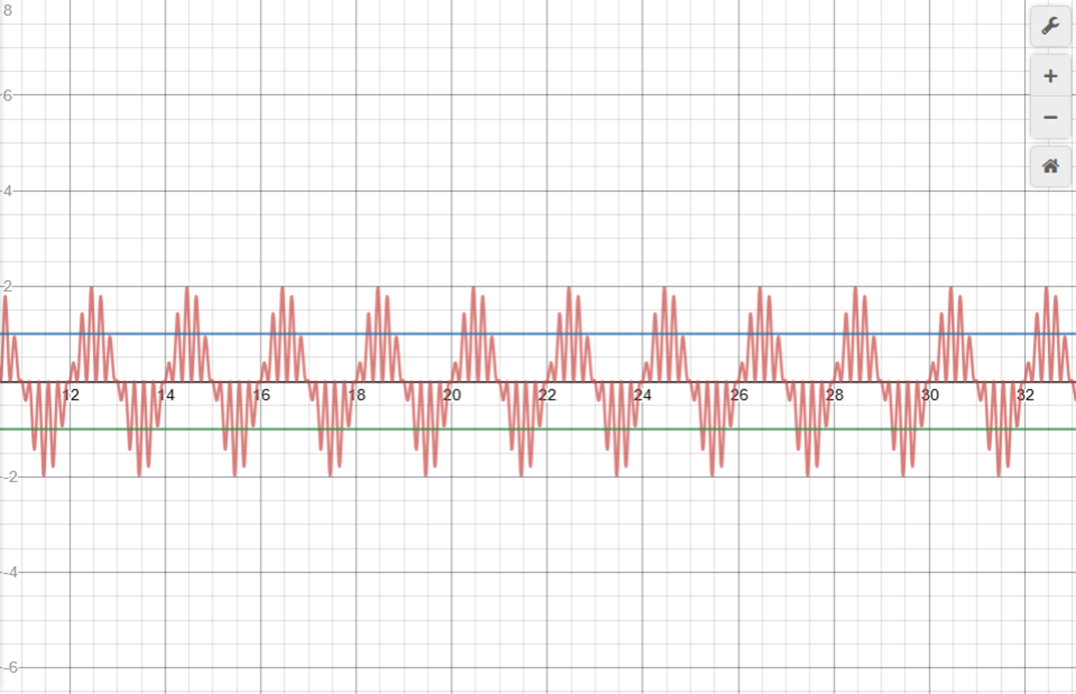
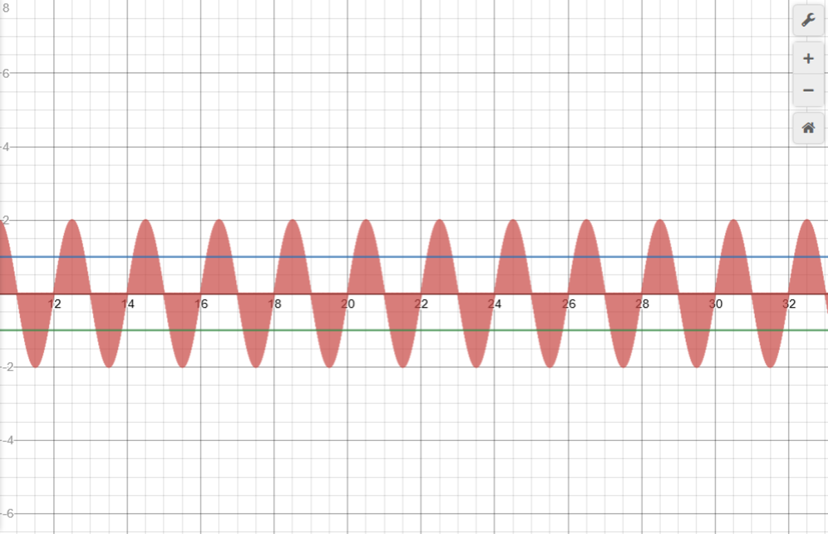
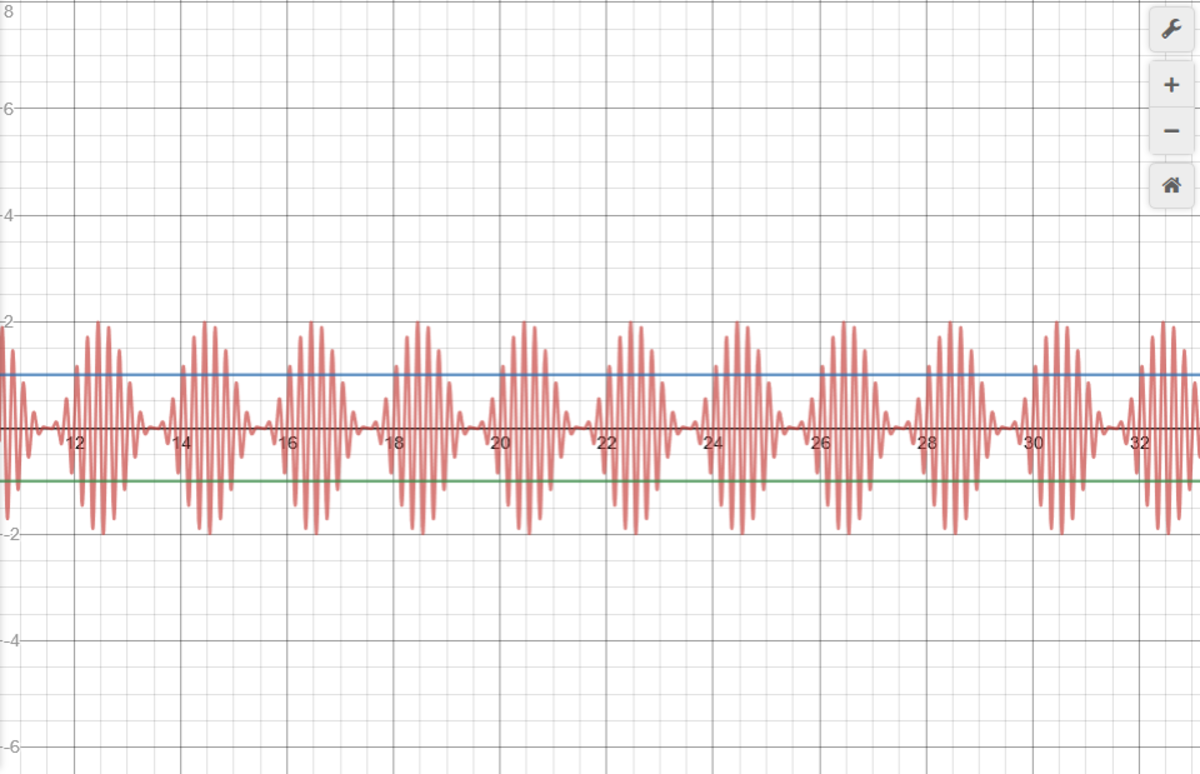
The result we see is that we only get the proper waveform we are looking for when the modulation frequency, , is significantly smaller than the carrier wave frequency, . The first two graphs do not give the desired shape. The last two graphs do.
The last thing to discuss is the carrier amplitude, . In the images above I set the carrier amplitude to one for simplicity. The truth is that the carrier amplitude is the one thing that will not really affect the general shape of this type of waveform. Sure the wave will become larger or smaller, but the overall shape will remain the same. Therefore the amplitude really depends on one thing and that is the amount of power the circuit requires. Of course each circuit will be unique in this respect so there is really no ideal amplitude or ideal ratio that we can use to set this variable.
In this next section I will talk about how information is represented by the side bands. I mentioned earlier that the information is carried by the side bands. Earlier I set the restriction that the signals we use are sinusoidal functions but this is not always practical since sinusoidal functions have one frequency, but in audio and speech waveform the frequency is inconsistent. This is why we must attach the signal to the carrier wave in the first place. The resulting superposition of the signal attached to the carrier wave is a wave with a consistent frequency which can be used in electronic circuits. The still consists of multiple frequencies but because of the carrier wave the wave will intersect the horizontal axis at regular intervals. Since the carrier frequency is much larger than the modulation frequency the electronic circuitry will react more to the carrier frequency. Now let us go back to considering the basic case with sinusoidal functions at different frequencies representing pure tones. Let say our sound wave consists of two different pitches. It starts as an A4 at 440 Hz, then after some time becomes an A3 at 220HZ. This is a very simple audio wave.
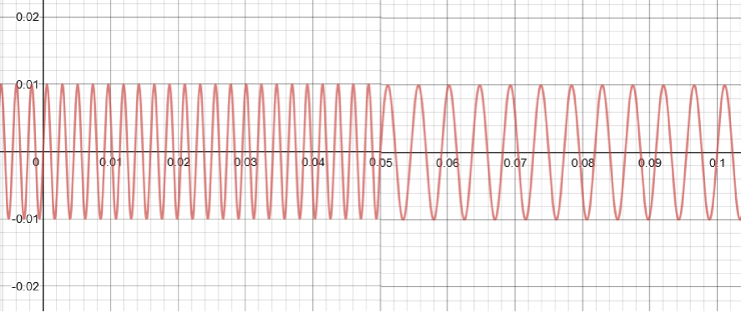
Since we are transmitting two different frequencies we will need a maximum modulation frequency of at least 2 to provide the proper bandwidth of 4 Hz. Bandwidth should be double the number of frequencies in the signal. So let us use a carrier frequency of 10 Hz for this case even though that is rather small. We will assign the 440 HZ sound signal to 12Hz and by symmetry also 8Hz. The 220 Hz will be assigned to 11 Hz and by symmetry 9 Hz. I will show how this can be represented using the equation. Because I used a carrier wave of only 10 Hz I adjusted the time axis so that the A4 plays for 2 seconds and then the A3 plays for 2 seconds. (Instead of 0.05 seconds as shown above).
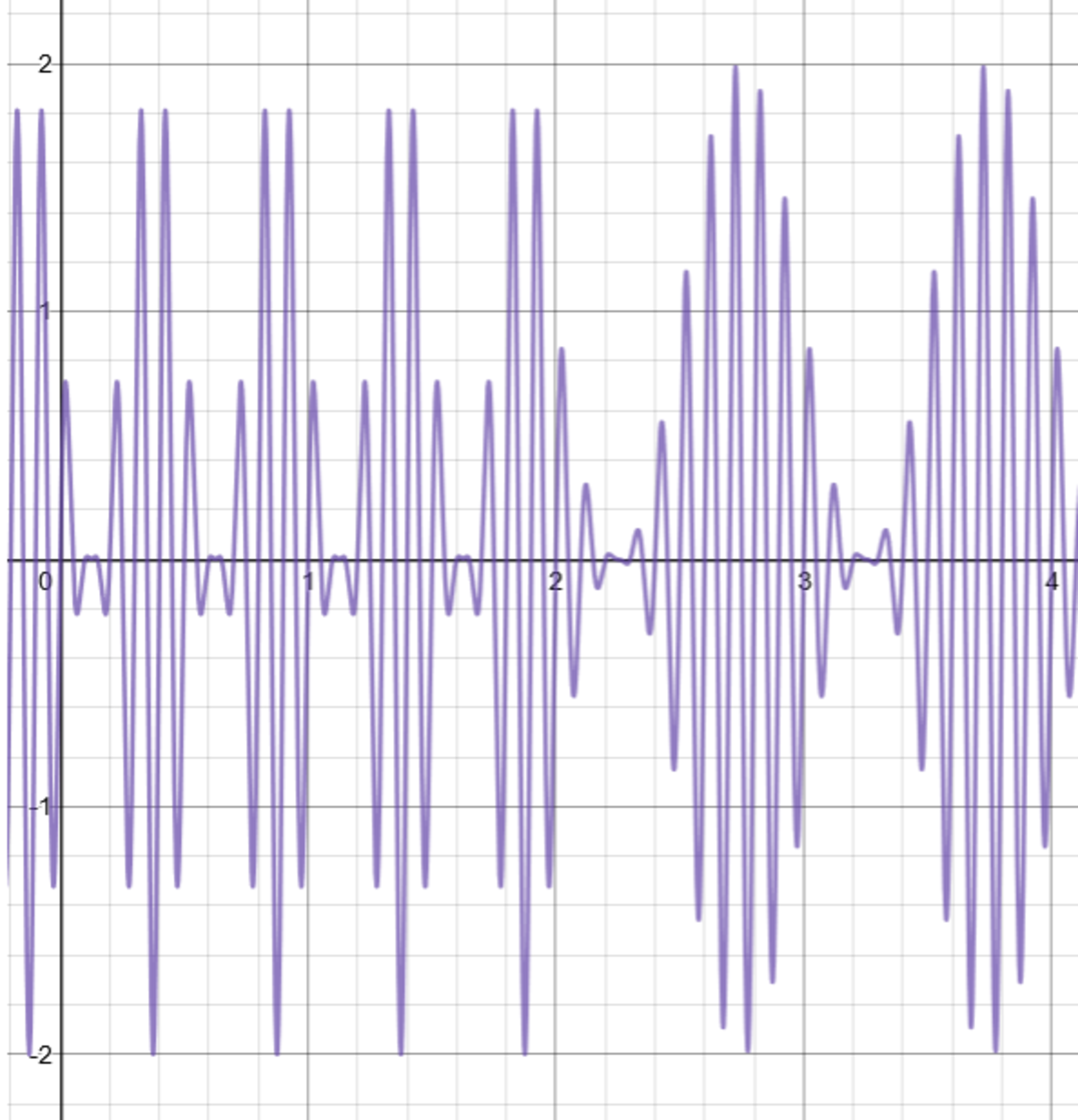
Since both the signals are on their own frequency we can choose whether we want to play one or the other, or both simultaneously. It is important to note that the frequency of modulation does not have to be the same as the sound wave frequency. As long as the signal is still a sinusoidal function it can be recovered from the carrier wave. There are circuits which can be use to scale the frequency of the signal to the desired value at a later point. For example when the signal is being demodulated. This will make sure that the speaker receives the output at the correct frequency. Although to be honest this makes the circuitry a lot more complicated so it would be a lot easier to just choose a carrier frequency that is at least 100 KHZ to center the frequency band and then the audio range of 10- 20 KHz will seem small in comparison. In that case the modulation frequency is can be set to the same frequency as the sound wave frequency. At any given time the wave will be a combination of different frequencies within the bandwidth range.
Easy Math Editor
This discussion board is a place to discuss our Daily Challenges and the math and science related to those challenges. Explanations are more than just a solution — they should explain the steps and thinking strategies that you used to obtain the solution. Comments should further the discussion of math and science.
When posting on Brilliant:
*italics*or_italics_**bold**or__bold__paragraph 1
paragraph 2
[example link](https://brilliant.org)> This is a quote# I indented these lines # 4 spaces, and now they show # up as a code block. print "hello world"\(...\)or\[...\]to ensure proper formatting.2 \times 32^{34}a_{i-1}\frac{2}{3}\sqrt{2}\sum_{i=1}^3\sin \theta\boxed{123}Comments
There are no comments in this discussion.