4th-Order Circuit
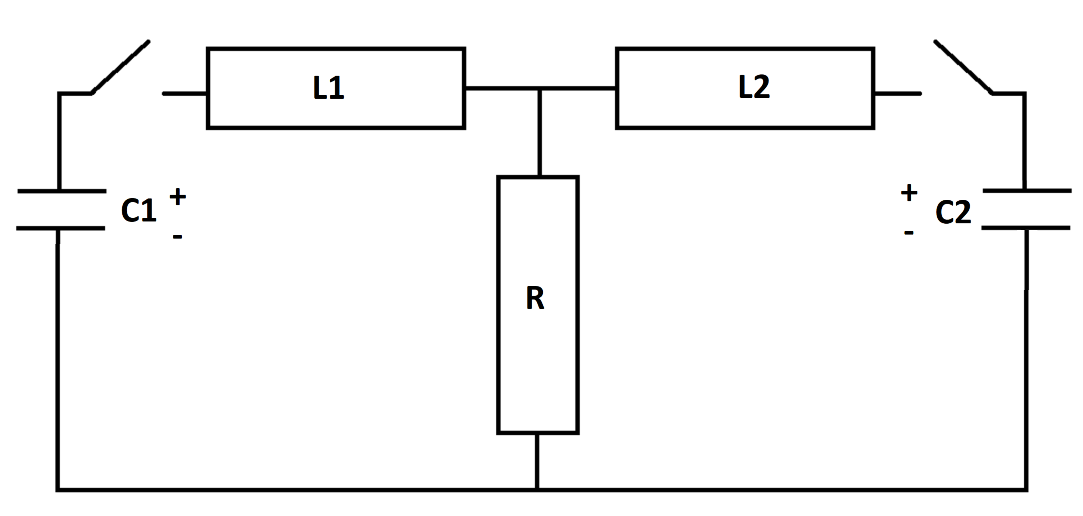
In the RLC circuit below, the switches close at time t = 0 , at which time the inductors are de-energized and the capacitors have initial voltages V C 1 and V C 2 .
Let E ( t ) be the total combined energy stored in the inductors and capacitors at any particular time. Let E 0 be the value of E ( t ) at time t = 0 .
At what time is E ( t ) equal to 0 . 0 9 E 0 ?
Details and Assumptions:
1)
R
=
2
2)
L
1
=
1
3)
L
2
=
2
4)
C
1
=
3
5)
C
2
=
1
6)
V
C
1
=
5
7)
V
C
2
=
1
0

The answer is 42.5.
This section requires Javascript.
You are seeing this because something didn't load right. We suggest you, (a) try
refreshing the page, (b) enabling javascript if it is disabled on your browser and,
finally, (c)
loading the
non-javascript version of this page
. We're sorry about the hassle.
2 solutions
One may even get an analytical solution in terms of a matrix exponential. Anyway, I posted my solution just to share some of my observations as I solved this. Nice problem, as always!
Thanks for the detailed solution. I also wrote some code to keep track of energy conservation, as an additional check on the solution. It is interesting to see how long the circuit oscillates after it loses most of the energy during the initial current spike. When I run Explicit Euler, I get a final time of 4 2 . 7 1 for Δ t = 1 0 − 4 , 4 2 . 4 9 for Δ t = 1 0 − 5 , and 4 2 . 4 7 for Δ t = 1 0 − 6
Log in to reply
I used a time step of 1 0 − 5 and reported my observations based on that (had solved it several hours earlier, actually). Now when I recheck using the numbers you have given, I see the results are consistent with your observations. Maybe I was absent-minded about some detail while I was solving it. Anyway, thanks for the clarification
Log in to reply
Got any more problems coming?
Log in to reply
@Steven Chase – I am a little tied up these days. I do manage to take out time to solve any problem I find interesting and to keep my streak alive. I will post something as soon as I can

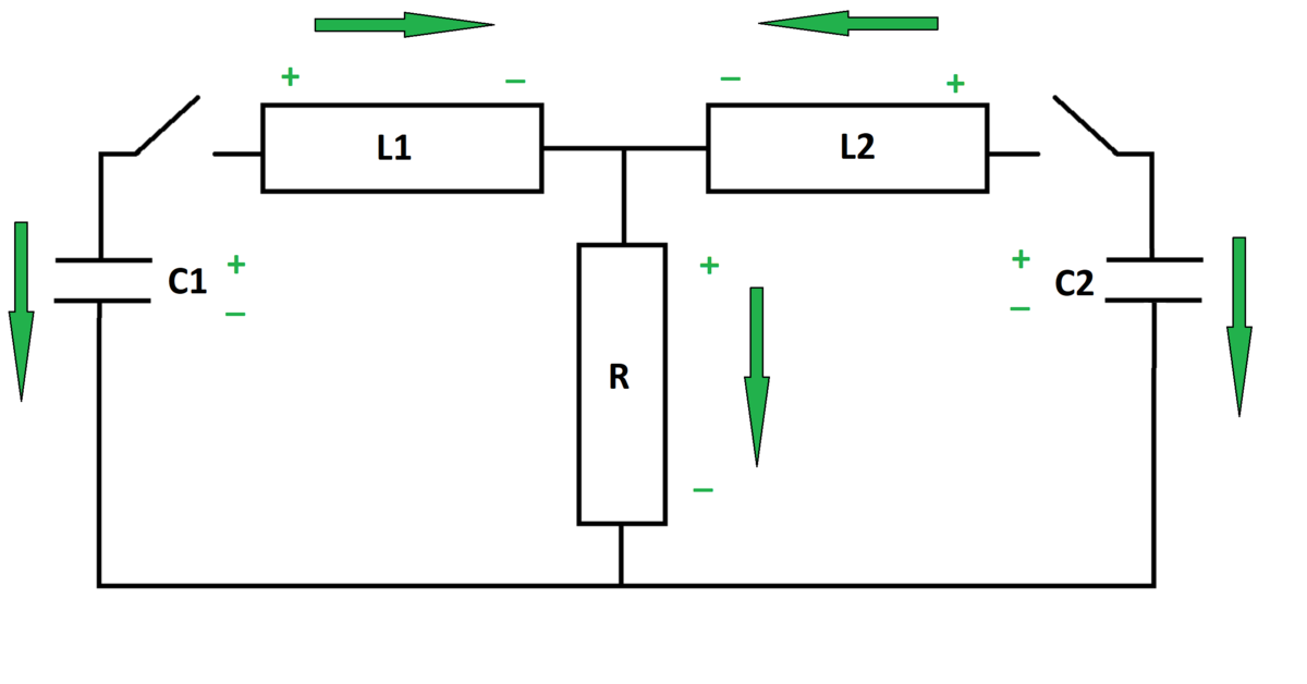
The state variables are the capacitor voltages ( V C 1 , V C 2 ) and the inductor currents ( I L 1 , I L 2 ) . Express the rates of change of the state variables in terms of the state variables themselves.
Capacitor equations:
− I L 1 = C 1 V ˙ C 1 − I L 2 = C 2 V ˙ C 2
Inductor equations:
V C 1 − R ( I L 1 + I L 2 ) = L 1 I ˙ L 1 V C 2 − R ( I L 1 + I L 2 ) = L 2 I ˙ L 2
Isolating the derivative terms and numerically integrating yields the desired solution. Recall also the equations for the energy stored in capacitors and inductors:
E C = 2 1 C V C 2 E L = 2 1 L I L 2
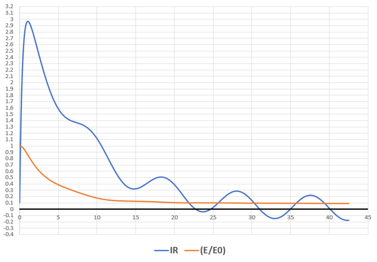
It takes about 4 2 . 5 units of time for the total stored energy to drop to 9 % of its original value. A plot of the resistor current and energy ratio is shown below:

This problem is interesting on many levels. I hope to explain it all in the following description. At a general time t , say the charge on C 1 is Q 1 , that on C 2 is Q 2 . Let the current flowing through L 1 be I 1 and that through L 2 be I 2 . Since the capacitors are discharging, it can be concluded that:
Q ˙ 1 = − I 1 Q ˙ 2 = − I 2 Using Kirchoff's laws, the circuit equations can be written as:
− C 1 Q 1 + L 1 I ˙ 1 + R ( I 1 + I 2 ) = 0 − C 1 Q 2 + L 1 I ˙ 2 + R ( I 1 + I 2 ) = 0
Now, I often make use of linear algebra to make this system of equations more compact. The benefit of using linear algebra is that doing so enables me to code in a more compact manner. By rearranging the above equations, one can obtain the following state-space form:
⎣ ⎢ ⎢ ⎡ Q ˙ 1 Q ˙ 2 I ˙ 1 I ˙ 2 ⎦ ⎥ ⎥ ⎤ = ⎣ ⎢ ⎢ ⎡ 0 0 L 1 C 1 1 0 0 0 0 L 2 C 2 1 − 1 0 − R / L 1 − R / L 2 0 − 1 − R / L 1 − R / L 2 ⎦ ⎥ ⎥ ⎤ ⎣ ⎢ ⎢ ⎡ Q 1 Q 2 I 1 I 2 ⎦ ⎥ ⎥ ⎤
Or:
x ˙ = A x Where A = ⎣ ⎢ ⎢ ⎡ 0 0 L 1 C 1 1 0 0 0 0 L 2 C 2 1 − 1 0 − R / L 1 − R / L 2 0 − 1 − R / L 1 − R / L 2 ⎦ ⎥ ⎥ ⎤ x = ⎣ ⎢ ⎢ ⎡ Q 1 Q 2 I 1 I 2 ⎦ ⎥ ⎥ ⎤
The initial conditions are stated in the problem and are written as a vector: x ( 0 ) = ⎣ ⎢ ⎢ ⎡ C 1 V C 1 C 2 V C 2 0 0 ⎦ ⎥ ⎥ ⎤
Now, the total energy of the circuit is as follows:
E = 2 C 1 Q 1 2 + 2 C 2 Q 2 2 + 2 L 1 I 1 2 + 2 L 2 I 2 2
This can be written in a compact form using linear algebra as follows:
E = 2 1 x T W x
Where x is the vector defined above and
W = ⎣ ⎢ ⎢ ⎡ C 1 1 0 0 0 0 C 1 1 0 0 0 0 L 1 0 0 0 0 L 2 ⎦ ⎥ ⎥ ⎤
The energy at t = 0 is: E o = 2 1 x ( 0 ) T W x ( 0 )
Now, I define normalized energy as follows:
E R = E o E
The following plot shows two cases. One where R = 2 and the other where R = 0 . Notice how well the law of conservation of energy is demonstrated through this . It is known that a resistor is a dissipative element and without it, energy remains constant.
What also makes this problem interesting is the answer. I am lucky to have got it right cause I obtain an answer of approximately 4 2 . 7 seconds and not 42.5 seconds. Subsequent tries got me to the correct ballpark. Moreover, the use of linear algebra made the numerical solution more compact in my opinion. The simulation code is below (MATLAB).