A resistor swarm
All the resistors in the above circuit have equal resistance R = 1 0 Ω . Calculate the equivalent resistance R e between points A and B in ohms. Submit your answer to the nearest integer.
The answer is 15.
This section requires Javascript.
You are seeing this because something didn't load right. We suggest you, (a) try
refreshing the page, (b) enabling javascript if it is disabled on your browser and,
finally, (c)
loading the
non-javascript version of this page
. We're sorry about the hassle.
4 solutions
This is a very neat solution. Kudos.
Can you elaborate on how to you find which terminals are at the same potential?
Log in to reply
Of course! The important thing in this task is that all of the resistances have the same value. Were it not for that, I don't think that it'd be possible to do it. Note that between two connected terminals, we have exactly one resistor, meaning that after each resistor, we have a point of the same potentials. Let's observe point A. It is directly connected to two terminals. It is connected to them with the same resistance, meaning that the terminals have the same potential.
Log in to reply
This is a good solution, but you have not given a solid reasoning why the three points marked E have the same potential...
If one point is connected to two other points with two equal-valued resistors, it does not necessarily follow that these two points have the same potential. Therefore there is more work to do!
Log in to reply
@Arjen Vreugdenhil – Another solution I had in mind is to imagine a current flowing from point A to point B. The current will evenly distribute among the adjacent resistors, but that still brings us to my point, which you seem to disapprove. Would you be so kind to explain it your way. I'd really like to see it!
Log in to reply
@Djordje Veljkovic – Your argument "the current will evenly distribute among the adjacent resistors" is true, but needs proving. If current from point A is faced with two resistors of equal value, it does not necessarily split evenly over the two; that depends on the rest of the circuit.
For instance, if I'd remove one of the resistors adjacent to point B, the potentials in the two points you labeled "C" are no longer equal.
The proper argument is from symmetry:
-
The line E E E you draw in the diagram is a plane of reflection for the entire circuit. Therefore the potential of all points E lies precisely halfway between the potentials of A and B. (This means that one only needs to analyze one half of the circuit, then simply double the resistance value!)
-
The other diagonal, perpendicular to E E E , is also a plane of reflection. Therefore the two points C and the two points D have the same potential.
Log in to reply
@Arjen Vreugdenhil – A beautiful explanation! Thank you!
@Djordje Veljkovic – I can see that the current will divide equally from A to the two resistors at C. I don't immediately see why it should divide equally while going from a C point to E. But once we see that all E points are equipotential by symmetry, it follows that current divides equally at A as well as C.
I have a question. What will be the equivalent resistance between the points A and E(the one at the corner)? Please answer I couldn't really understand how that symmetry thing works.
Log in to reply
As a previous commenter said, the line EEE is a plane of reflection for the entire circuit. The equivalent resistance would simply be R/2 + R/4, because we neglect all of the resistors connected between B, D and E. We have two parallel connected resistors between A and C (which give R/2), and 4 parallel resistors between C and E (which give R/4). The two new resistors, R/2 and R/4 are connected in series, so we add the resistances together to get 7.25 ohms.
If the terminals were at A and E then the line DEC will be the line of symmetry and the junctions D, E and C will be equipotential and the resistors connected between the DE and EC can be removed. Once we remove these two resistors rest of the circuit can be solved using simple series and parallel sequences.
Since it is clear from the symmetry of the network that no current passes through the central node between two wires that meet in a straight line, we may cut that node diagonally (from A to B). This gives an equivalent network that is simple enough that one can calculate the resistance mentally.
Log in to reply
What do you mean? Each of the nodes has current flowing in and out, and each of the resistors has non-zero current.
Log in to reply
The node at the center can be cut in these two ways. Both of these circuits have the same equivalent resistance as the circuit in the original problem.
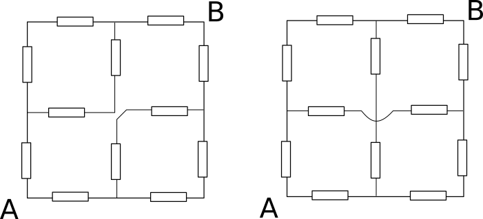
I believe that Anthony is referring to the one of the left. Its equivalent resistance can be calculated mentally.
The current flows into the central node E from C and then flows out from E to D.
Do not agree on 3 E points. The middle one is not symmetric to the other corners from geometry point of view.
Log in to reply
The two C points and the two D points have the same potential because of symmetry about the diagonal formed by joining A and B.
The three E points have the same potential because the resistor system is symmetric about the diagonal formed by joining the outer E points. Therefore the potential difference across A and B is double of potential difference across A and (any) E.
We can find the equivalent resistance using the junction and the loop rule without redrawing the circuit. First let's look at the currents:
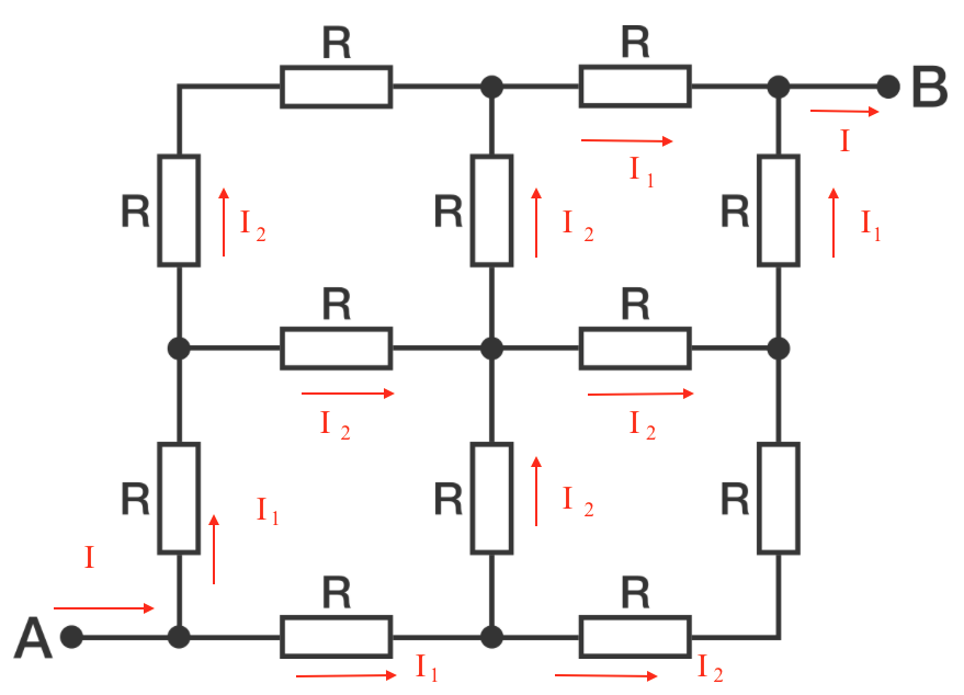
From junction rule we have: I = 2 I 1 and I 1 = 2 I 2
Now we can apply a potential difference V A B and find a loop. We can follow this path:
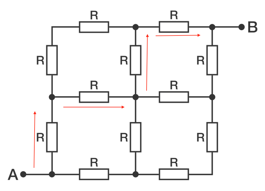
So from the loop rule we have:
V A B − 2 I 1 R − 2 I 2 R = 0
Using the junction rule from above that becomes:
V A B = 2 3 I R
The equivalent resistance between A and B is
R e q = I V A B = 2 3 R = 1 5 Ω
Why did you distribute the current I 1 as I 2 and I 2 in the two branches? Shouldn't they be I 2 and I 3 ?
Log in to reply
No, they shouldn't. Using Kirchoff's Node Conservation Law, we see that we have two currents I 2 flowing into the middle node, meaning that there is no more dividing.
Log in to reply
It is still unclear to me as to why the current I 1 divides into two I 2 , Can you elaborate further?
Log in to reply
@Rohit Gupta – It is clear that this circuit is symmetric (line EEE is one of the planes of reflection). Because of the nature of the circuit, any current faced with equal-valued values will split into two. In Eleni's solution, first current I splits into two currents I1 (I1 = I/2), and then the two I1 currents split into two I2 currents each (I2 = I1/2 = I/4).
An excellent, elegant solution. Thanks for the contribution!
How do you know the I1 can be split into two I2 as the middle point is not symmetrical to the corner?
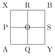
First, we label the points (each line represents a resistor of R Ω ) :
Then we redraw the grid so that it's easier to see:
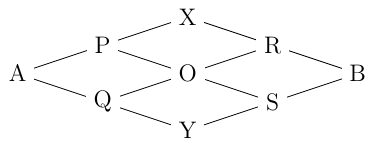
And the table below shows how many resistors there are on each column, and the resistance of each column:
| 2 | 4 | 4 | 2 |
| 2 R | 4 R | 4 R | 2 R |
So since all the columns are in series, we have:
2 R + 4 R + 4 R + 2 R = 2 3 R = 2 3 0 = 1 5 Ω
Can you elaborate why all the resistors in a column are in parallel?
Log in to reply
My answer to that would be because the current spilts up from the previous node to the next, for example A splits into P and Q, P splits into X and O, and because of the symmetry the lines (i.e. all the resistors) on each column have the same current. Therefore they can be treated as parallel resistors. If you are still not sure of my explanation, my only piece of advice would be to derive the formula for the harmonic summation of parallel resistors - that should help. Then perhaps read this again. By all means tell me if you still do not understand - in all honesty this solution is "quick and dirty" and I have not rigorously thought it through to accound for special cases etc.
Log in to reply
I see the symmetry which explains why P, Q and X, O, S are at the same potential.
How about this arrangement?

Will the resistances in each column still be in parallel now? I doubt the resistances in the second column are in parallel.
Log in to reply
@Pranshu Gaba – No, they are not in parallel. Due to the symmetry, I claim that two distinct points which are equidistant from A and equidistant from B have the same potential, and so are in parallel. Then this problem can be solved in a similar way (i.e. redraw the diagramme, label the nodes, count the number of resistors in parallel, and sum them harmonically). Given the resistance of each resistor is R, I get 11R/6 as the total resistance.
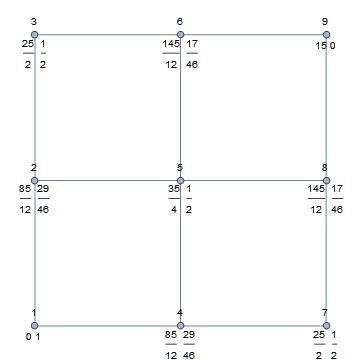
The number over the node is the assigned node number. The number below and to the left of the node is the effective resistance from node 1. The number below and to the right of the node is the voltage assuming that the input voltage at node 1 is 1 and that node 9 is at 0 voltage (grounded). These were extracted from a mesh analysis of the lattice.
As has been noted elsewhere, nodes at the same voltage (if AC, then, including phase) may be shorten together without affecting the answer of these problems.
First, let's mark the points on the same potential. I have done so on the picture below:
Next, we draw a simpler scheme:
On the picture above, we have several groups of parallelly connected resistors, and because all of the resistances are the same, we can present the following equivalent scheme:
On the picture above, we have 4 resistors connected in a series, so the equivalent resistor will be equal to their sum:
Switching the numerical values, we see that R e = 1 5 Ω .