A different wheel
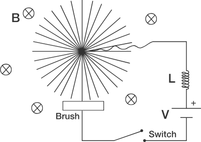
The figure above shows a circuit. The wheel has a brush that ensures that a spoke is in contact with the wires all the time, thus completing the circuit. There is a magnetic induction B directed into the plane of the diagram. The inductor has an inductance of L and the cell has an emf of V . The radius of the wheel is R and its moment of inertia about its axis is I .
Find the angular velocity of the wheel at t = 3 π 2 s .
Details and Assumptions:
-
There is no resistance in the circuit.
-
V = 2 0 V , I = 1 6 k g m 2 , L = 1 H , R = 1 m , B = 4 T .
Source: INPHO.
The answer is 5.
This section requires Javascript.
You are seeing this because something didn't load right. We suggest you, (a) try
refreshing the page, (b) enabling javascript if it is disabled on your browser and,
finally, (c)
loading the
non-javascript version of this page
. We're sorry about the hassle.
2 solutions
Good question. I'd posted a similar question .
My first Olympiad level physics problem which I solved :D
Was this a very easy problem @Spandan Senapati wrt Olympiad physics?
Log in to reply
No not exactly. It can be said as a moderate level olympiad problem.Questions in Inpho are quite similar to jee physics problems. But in the recent years some problems like Inpho-2016 prob-6(Hideshi-Yukawa Potential), inpho-2013(Brunt-Vaisala Oscillations) can be considered challenging although doable.
Hey it's actually TAKEN from PRINCETON PROBLEMS IN PHYSICS. It was previously asked in an exam at the mentioned university
Am I correct?
The trick to this problem, which I initially didn't fully comprehend, is that the charges in the spoke (rod) effectively have two different motions:
1) A longitudinal electrical drift which results in a transverse torque on the spoke (via the B-field)
2) A transverse motion, due to the rotation, which induces a longitudinal
motional emf
in the rod (also via the B-field).
When the current and B-field are at right angles, the transverse force on a current carrying wire of length l is:
F = i l B
The differential torque on a piece of the conducting spoke is: d τ = ( i d r B ) r = B i r d r
The total torque on the spoke is:
τ = ∫ 0 R B i r d r = 2 B i R 2
Applying the rotational form of Newton's Second Law gives:
τ = I d t d ω = 2 B i R 2 i = B R 2 2 I d t d ω d t d i = B R 2 2 I d t 2 d 2 ω
There are three voltage changes in the circuit:
1) The source voltage
2) The inductor voltage
V
L
=
L
d
t
d
i
3) The motional emf induced in the rod
Let's calculate the motional emf. For a rod of length l moving at speed v at right angles to a uniform B-field, the motional emf is:
E = B l v
For an infinitesimal piece of the spoke, this translates to:
d E = B d r r ω = B ω r d r
The total motional emf in the spoke is then:
E = ∫ 0 R B ω r d r = 2 B ω R 2
Writing the KVL equation for the circuit gives:
V = L d t d i + 2 B ω R 2
Substituting for d t d i in terms of ω gives:
V = B R 2 2 I L d t 2 d 2 ω + 2 B ω R 2
Do these sign conventions make sense? It seems to me that this system will likely behave similarly to an un-commutated DC motor, which means that its angular speed will oscillate between clockwise and counter-clockwise when a DC voltage is applied. This behavior is implied by the above equations.
The homogeneous equation is:
d t 2 d 2 ω = − 4 I L B 2 R 4 ω = − α ω
The general solution is then:
ω = A c o s ( α t ) + B s i n ( α t ) + C ω ˙ = − A α s i n ( α t ) + B α c o s ( α t ) ω ¨ = − A α c o s ( α t ) − B α s i n ( α t )
Applying initial conditions gives (note that the initial speed is zero and the initial torque is zero):
0 = A + C 0 = B V = B R 2 2 I L ( − A α ) = B R 2 2 I L ( − A ) 4 I L B 2 R 4 = − A 2 B R 2
Solving for the constants gives:
A = − B R 2 2 V B = 0 C = B R 2 2 V
The expression for ω is then:
ω = B R 2 2 V ( 1 − c o s ( α t ) ) α = 4 I L B 2 R 4
Plugging in numbers and solving at t = 3 2 π gives ω = 5 .
Hey its incorrect.....I have set values such that the exact answer is 5.The mistake here is that when a spoke rotates in the magnetic field there is a Motional emf induced so L d i / d t + B ω R 2 / 2 − V = 0 .and i B R 2 / 2 = I d ω / d t .....Solving this gives ω = ( 2 V / B R 2 ) ( 1 − c o s ψ t ) .where B R 2 / 2 √ I L = ψ ......Thanks.
Log in to reply
Interesting. So the electric charge in the wire actually has two different velocity components: A longitudinal component (current drift velocity) which interacts with the B field to produce a transverse torque, and a transverse component (mechanical) which gives rise to an internal longitudinal voltage drop in the wire.
Log in to reply
The latter of which I neglected to account for.
Yes....That's what Olympiads test for........Creativity... I just shared this problem for I thought it will be interesting for the community.....Now can you plz post a solution...That will help a lot...
Log in to reply
@Spandan Senapati – Sure, I'll update it tomorrow.
@Spandan Senapati – Ok, the solution has been updated.
Log in to reply
@Steven Chase – Sir what's the latex for putting the limits of integration.
Log in to reply
@Spandan Senapati – You can hover over it with your mouse to see
And the title itself says a different wheel.....its angular velocity increases then decreases,zero sometimes....?rather than the common wheels......
@Steven Chase .Thanks a lot sir.....Great solution......
Hey, taking general solution is the right way. But simplifying in the following way is easier. d t d i = V − 2 ω B R 2 ω → ( ω − B R 2 2 V )
We proceed as follows..... Let the current in the circuit at an instant be i .Then using Kirchoff's Loop Law. L d i / d t + E − V = 0 . E is the magnitude of the motional Emf induced in the spoke.....We know E = B ω R 2 / 2 .Also I d ω / d t = τ .For a small element d τ = ( i B d r ) r .Now integration with limits from 0 − R yield ∫ d τ = i B ∫ r d r or τ = i B R 2 / 2 .Plugging the required eq becomes i B R 2 / 2 = I d ω / d t .So Our KVL modifies to 2 L I / B R 2 d ω / d t = E − B ω R 2 / 2 .Now its easy to observe that the eq represents the equation of SHM(set E − B ω R 2 / 2 = ϕ you get the trivial eq d 2 ϕ / d t 2 = − ψ 2 ϕ ).Now we use the boundary conditions. 1)At t = 0 , i = 0 .& 2) ω = 0 .This gives ω = 2 V / B R 2 ( 1 − c o s ψ t ) .where ψ = B R 2 / 2 √ ( I L ) .Plugging the required values you get the answer as ω = 5