Brilliant's Brilliant LOGO
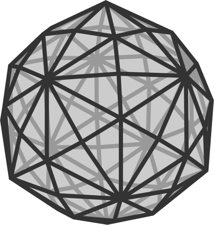
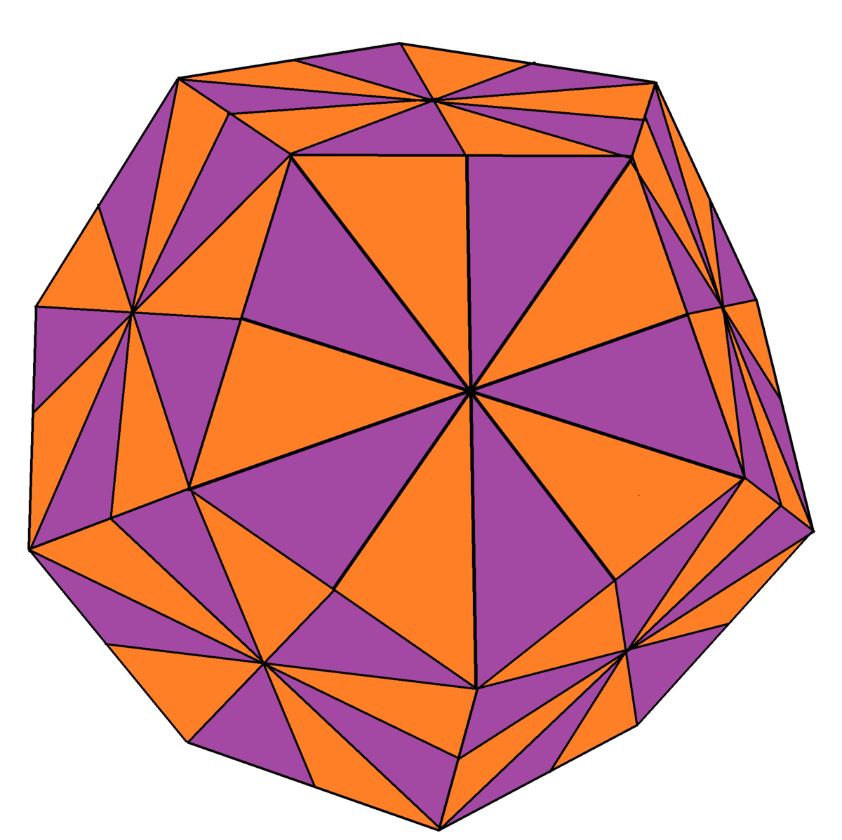
The Brilliant logo is similar in appearance to a Disdyakis triacontahedron , a Catalan solid. Suppose we had a circuit consisting of the edges and vertices of one of these solids, and the resistance along any edge is 1 Ω .
The North and South pole vertices of this solid each have 10 connected edges. Determine the equivalent resistance between the poles of the solid in Ω .
The answer is 0.384.
This section requires Javascript.
You are seeing this because something didn't load right. We suggest you, (a) try
refreshing the page, (b) enabling javascript if it is disabled on your browser and,
finally, (c)
loading the
non-javascript version of this page
. We're sorry about the hassle.
6 solutions
Sir, what is the formula for expanding a star of valency 4. I searched on it but couldn't find the formula. Thank you.
Log in to reply
If n resistors meet at a vertex to form a star, and the resistance from node u to the central vertex is R u , then the equivalent mesh consists of ( 2 n ) resistors, with the resistance from node u to node v being R u R v w ∑ R w − 1
Follow a link at the bottom of the Wikipedia page on Δ Y-transforms for (a little) more.
My answer was counted as correct, because it was within the margin but I could not post it, alas. Sorry to post it as a reply, but I did not see a solution like it. If my answer is not exactly right I would like to know where the flaw is.
Our shape has 62 vertices and 180 edges. By carefully looking at the network and its symmetries, we can see that many vertices must have the exact same voltage.
There are three types of vertices, I will assign colours to the different types: 12 'red' vertices with 10 neigbours each (5 blue and 5 green). 20 'blue' vertices with 6 neighbours each (3 red and 3 green). 30 'green' vertices with 4 neighbours each (2 red and 2 blue).
Apply +1 and -1 volt to two opposite red vertices, that I dub the 'north pole' and the 'south pole'. In the middle between the poles there is an 'equator', ring of 20 vertices, alternating green and blue. By symmetry these points must be at 0 V. So we 'only' have to deal with the 80 edges (resistors) that are connecting this equator to the north pole. Classify the vertices into 6 regions of different voltage:
0V at 20 vertices, alternating blue and green at the equator;
(a)V at 5 red vertices, each of which connects to 5 equator vertices (3 blue and 2 green);
(b)V at 5 green vertices, each of which connects to a blue equator vertex and 2 vertices of region (a);
(c)V at 5 blue vertices around the north pole;
(d)V at 5 green vertices around the north pole;
1V at the north pole vertex.
Below the regions are displayed as lies and the numbers indicate the number of resistors connecting the lines above and below them. Imagine that for each number n, there is a resistor of 1/n that connects to the line above it and below it, e.g the [5] in the left middle is a 0.2 ohm resistor connecting a and d. In total indeed 80 on each of the hemispheres and 20 on the equator.
-------------------------- 1
[5]
d ------------ [5]
[10]
----------------- c
[5] [5]
[10] ----------- b
[10]
a --------------- [5]
[25]
0 ------------------------
The total current from pole to equator must be the same for each parallel, so we have the following set of equations
I=5(1-d)+5(1-c)
I=5(d-a)+10(d-c)+5(1-c)
I=5(d-a)+10(c-a)+5(c-b)
I=5(d-a)+10(c-a)+10(b-a)+5(b-0)
I=25(a-0)+5(b-0)
We use an extended matrix and Gaussian elemination to find a=91/521, b=101/521, c=222/521, d=264/521, I=2780/521.
Now remember that the current I was the result of putting 1V between the equator and the pole. So the actual current when we put 1V over the poles is half of this 1390/521, so that the effective resistance is 521/1390 = 0.3748 Ohm.
Relevant wiki: Transformation of Resistances (Star to Delta and Delta to Star)
Observe that the polyhedron consists of many triangles like the one given below.
And every outer edge of each triangle is shared by 2 triangles in a parllel way. So when we separate the triangle we double it and half the resultant edge to make it an icosahedron.
Note that Icosahedron is similar to Disdyakis triacontahedron. The difference is that all triangle faces are simple equilateral triangle. So try to convert this triangle to a simple triangle.
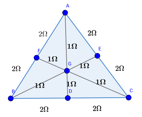
Convert the junctions E , D , F into Deltas. Then further convert the junction at point G into delta. You will get a simple triangle with a resistance of 5 8 Ω on each edge.
Now half this value(since two equal egdes in parellel are replaced by a single resistance) of to get a resisitance r = 5 4 Ω between two adjescent nodes of an icosahedron given below.
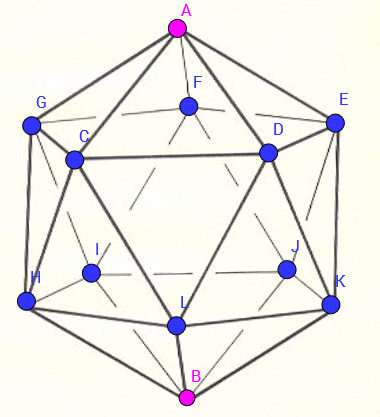
Now observe, that by symmetry the potentials at points G , C , D , E , F are equal. So no current will flow from G C , C D , D E , E F , F G .
So we can join the points G , C , D , E , F .
Similarly, the potentials at H , I , J , K , L are equal. So no current will flow from H I , I J , J K , K L , L H . So these points can also be joined.
So the circuit simplifies to:-
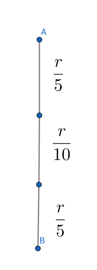 Now from A to B, the resistances are in series, so adding them gives
R
=
2
1
r
Now from A to B, the resistances are in series, so adding them gives
R
=
2
1
r
We know that r = 5 4 Ω .
So putting this we get R e q = 5 2 Ω .
NOTE:-This solution is incorrect. As a bonus question find the step where I made a mistake which made me get my answer wrong.
The problem is that, for example, vertex E is not a "Y", since it has another wire attached to it as part of the neighbouring triangle (and the Δ -Y transformation does not allow you to add an extra wire in the middle of the "Y"). You have to expand E as a mesh, and this makes everything much more complicated...
Log in to reply
Sir I actually treated the vertices E,D and F as a mesh and then after simplifying the wires in parellel between GA, GB, GC, I got a mesh of 3 wires at vertex G. And sir can you please make me understand the fault that I'm doing as I'm not able to recognize my mistake. And thanks for correcting my problem and adding a solution.
EDIT: Thanks I understood what I did wrong .
What's the difference between this answer and 0.384?
Log in to reply
This approach handles the valency 4 vertices incorrectly. I posted a report with my solution of 3 6 2 1 3 9 , and the answer was corrected. This solution relates to the old, incorrect, answer.
Log in to reply
Fantastic! I'm just learning Moore-Penrose pseudoinverse right now. I didin't expect it can be used here.
Log in to reply
@Xu Liangjun – The effective resistance between two vertices on a connected graph is a metric on the set of vertices, which is pretty cool...
Sorry for that. I actually did a big mistake for this question.
Log in to reply
You still did a great job. My head almost burned out for this puzzle. That's awesome.
It is confusing for people for a lengthy, but incorrect, posting like this to be here without comment. You should really either delete it or add a warning at the top that it is inaccurate...
Log in to reply
Thank you sir for making me aware of that and I have added a note at the end of my solution.
I got a very close value of 0.3667 (11/30 ohms) for the resistance between the poles, and I would like to know what is wrong with my approach. https://drive.google.com/open?id=1W7ZRZ8GezFI-NIc6Ce7cZcyyTicVruLa Thank you!
Log in to reply
Potentials would be equal only on the points on the same line with equal valency and not throughout the line because between these equipotential points there are branches through the line in the case of a disdyakis triacontahedron unlike an icosahedron
Well thought over, kudos for the idea of 2 ohm at the edges. But you made the assumption that there is a rotational symmetry about the central point of each triangle (G in the upper picture). Which is not true whe you take the currents into account: a current flows from E and F to G and from G to B, C and D. My prediction is that, because you neglect these extra currents, your answer slightly overestimates the resistance of the whole network. Check my solution, which is in a reply to Mark Henning's solution, for a quantitative answer.
I managed this with a bit of thought about symmetry and counting the edges. So from either pole to the 'arctic circle pentagon' there are ten links. So each of those legs contribute 0.1 Ohm. From the previous 'arctic pentagons' to the 5 apexes in the northern and southern hemispheres there are 20 edges so both of those contribute 0.05 Ohm each. The next stage is rather less clear. I estimated that there are 25 edges in total leaving both sets of the 5 apexes and every crossing takes 2 edges. So that 2/25 = 0.08 Ohm for the middle. I reckon it might be a little low since some edges are used twice, nevertheless there are also some extra edges. So all in all I estimated
0
.
3
8
, which was within the error band permitted.
This is an example of an engineering approach, good estimates are often as valuable as the theoretic exact answers.
There are 30 edges from your second to your thirt stage instead of 25. And you did the same as Gabriel Chacón, but why is this solution not acurate?
Log in to reply
I can't see Gabriel's solution, and I tried looking for it, so I can't comment. My solution is approximate because I have made a judgement about the number of pats and their lengths in the equatorial crossing hop. I was attempting to get a close enough answer by educated dead reckoning. Which is what I got.
Disdyakis triacontahedron can be created out of Dodecahedron by dividing each face in 10 triangles. Dodecahedron have has a top and bottom pentagon face and the centers of these are the vertices between which we have to calculate the resistance.
In the diagram below, the green region is the half of the pentagon in the upper half of the Dodecahedron and the red region is the half of the pentagon in the lower half of the Dodecahedron. Potential is written in box and the edge number in circle, so let the current in the direction of the arrow in edge number
n
is
i
n
. Because of the cyclic and mirror symmetries involved, this strip can be copied 10 times and pasted adjacently to make the Disdyakis triacontahedron. And the voltages in the middle vertices are derived from the mirror symmetry at the middle horizontal plane. As each of the edge has resistance
1
Ω
, so the current passing through an edge and the potential difference across it are equal and I will use them interchangeably throughout the solution.
![]()
Now for the applied voltage V , let's say current produced is I . So,
I = 5 ( i 1 + i 2 )
and
2 V = i 2 + i 6 + i 9 + i 1 2
The currents i 3 to i 9 can be obtained in terms of i 1 and i 2 using easy applications of Kirchhoff Voltage Law and Kirchhoff Current Law,
i 3 = i 1 − i 2
i 4 = 9 i 1 − 1 0 i 2
i 5 = 4 i 2 − 3 i 1
i 6 = 3 i 2 − 2 i 1
i 7 = 1 4 i 2 − 1 2 i 1
i 8 = 3 3 i 1 − 3 8 i 2
i 9 = 4 5 i 1 − 5 2 i 2
From the known potentials in the middle vertices, we know,
i 1 3 = i 1 1
i 1 2 = i 1 5
i 1 0 = i 1 4
By Kirchhoff Current Law,
i 6 + 2 i 5 + 2 i 7 = 2 i 9 + 2 i 1 0 + i 1 1 and i 8 + 2 i 9 = 2 i 1 2 + i 1 3
Writing the above relations in terms of i 1 , i 2 and i 1 2 ,
4 i 1 2 = 2 9 9 i 2 − 2 5 7 i 1 and 2 i 1 2 = 3 9 i 1 − 4 5 i 2
These can be solved to give,
i 1 : i 2 : i 1 2 : : 3 8 9 : 3 3 5 : 4 8
Finally, the resistance -
R = I V = 5 ( i 1 + i 2 ) 2 ( i 2 + i 6 + i 9 + i 1 2 ) = 5 ( i 1 + i 2 ) 2 ( 4 3 i 1 − 4 8 i 2 + i 1 2 )
R = 5 ( 3 8 9 + 3 3 5 ) 2 ( 4 3 ∗ 3 8 9 − 4 8 ∗ 3 3 5 + 4 8 ) = 3 6 2 1 3 9 ≈ 0 . 3 8 4
Using Wolfram Mathematica 11.3 in a heavy-handed approach (I agree with Mark Henning), the answer is 3 6 2 1 3 9 Ω .
vertices = PolyhedronData [ DisdyakisTriacontahedron , VertexCount ] ;
edges = PolyhedronData [ "DisdyakisTriacontahedron " , " Edges " ] ;
Looking for the vertices with 10 edges:
poles = Select [ Tally [ Sort [ Flatten [ edges ] ] ] , $#$1 [ [ 2 ] ] = 1 0 & ] T [ [ 1 ] ] ⇒ 2 3 , 2 4 , 2 5 , 3 2 , 3 3 , 3 4 , 5 7 , 5 8 , 5 9 , 6 0 , 6 1 , 6 2
Looking for 1--edged vertices at maximal graph distances:
Select [ Flatten [ Table [ { i , j , GraphDistance [ g , i , j ] } , { i , poles } , { j , poles } ] , 1 ] , $#$1 [ [ 3 ] ] = 6 & ] ⇒ ⎝ ⎜ ⎜ ⎜ ⎜ ⎜ ⎜ ⎜ ⎜ ⎜ ⎜ ⎜ ⎜ ⎜ ⎜ ⎜ ⎜ ⎜ ⎜ ⎛ 2 3 2 4 2 5 3 2 3 3 3 4 5 7 5 8 5 9 6 0 6 1 6 2 6 1 6 2 6 0 5 9 5 8 5 7 3 4 3 3 3 2 2 5 2 3 2 4 6 6 6 6 6 6 6 6 6 6 6 6 ⎠ ⎟ ⎟ ⎟ ⎟ ⎟ ⎟ ⎟ ⎟ ⎟ ⎟ ⎟ ⎟ ⎟ ⎟ ⎟ ⎟ ⎟ ⎟ ⎞
g = Graph [ Range [ vertices ] , edges ] ;
resistance = With [ { Γ = PseudoInverse [ With [ { wam = WeightedAdjacencyMatrix [ $#$1 ] } , DiagonalMatrix [ Tr /@ wam T ] − wam ] ] } , Outer [ Plus , Diagonal [ Γ ] , Diagonal [ Γ ] ] − Γ − Γ T ] & ;
Extracting the requested resistance from the complete effective resistance table:
resistance ( g ) [ [ 2 3 , 6 1 ] ] ⇒ 3 6 2 1 3 9 ≈ 0 . 3 8 3 9 7 7 9 0 0 5 5 2 4 8 6
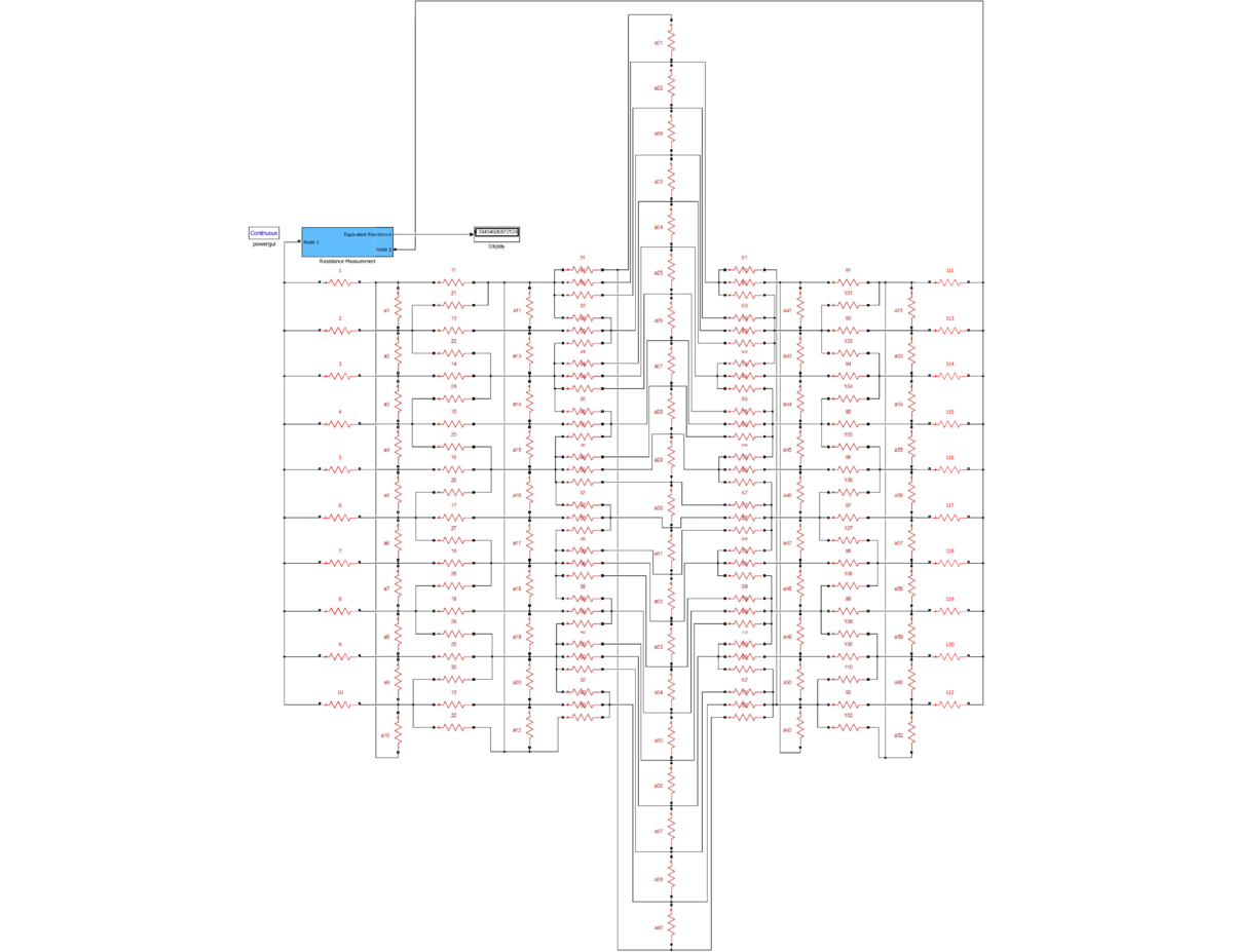
I just went all in with Simulink:
This problem can be solved by hand by applying the icosahedral symmetries of the triacontahedron, although you can have to handle very large fractions that eventually will simplify to the solution 139/362. On Wikipedia, you can find the below stereographic projection of the triacontahedron disdyakis from one of the poles (that is sent to infinity. The problem is to find the resistance between the 10 vertices pole at the center of the figure and the 10 vertices pole sent to infinity): https://en.wikipedia.org/wiki/Icosahedral symmetry#/media/File:Disdyakis triacontahedron stereographic d5.svg
By applying a 5-fold cyclic symmetry around the pole at the center of the figure, then a 2-fold symmetry relative to the line joining the two poles, you can simplify the resistor network to a simpler and planar resistor network similar to the one poster higher by Gurmeet Singh, with external edges getting a 1/5 resistance value and the inner edges getting a 1/10 resistance value.
It is then just a matter of applying several times the delta-Y transformation https://en.wikipedia.org/wiki/Y-%CE%94_transform and simplification rules for resistors in series and in parallel.
This solution is similar to the one provided by Gurmeet Singh, except no recourse to linear algebra.
Log in to reply
Can you please tell in brief how you got the icosahedral symmetry?. I tried that, you may check my solution above. But I did a mistake in that. Can you write the solution?
One heavy-handed approach uses Mathematica, which contains the data for the Disdyakis triacontahedron graph. If we take the Laplacian matrix Γ for that graph, and construct the Moore-Penrose pseudoinverse Γ − 1 , then the effective resistance between vertices u and v on the graph is Ω u , v = Γ u , u − 1 + Γ v , v − 1 − Γ u , v − 1 − Γ v , u − 1 Mathematica tells me that the effective resistance between opposite vertices of valency 1 0 is 3 6 2 1 3 9 (while the effective resistance between opposite vertices of valency 6 is 3 8 0 1 0 2 0 7 2 3 , while the effective resistance between opposite vertices of valency 4 is 7 6 0 2 5 5 2 5 ).
A relatively simple (well, it involves solving 1 4 simultaneous equations in 1 4 variables) calculation confirms that the effective resistance between A and B is 3 6 2 1 3 9 Ω .