Capacitor Switching Transient

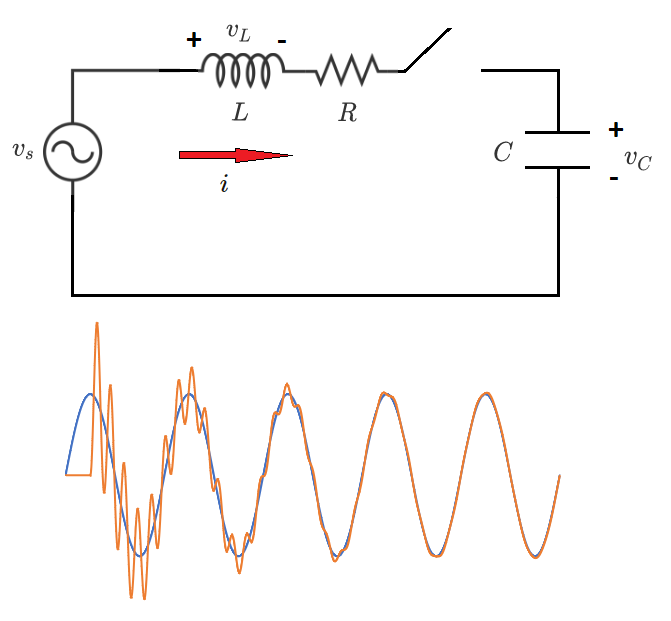
A resistor ( 0 . 3 4 2 0 Ω ), an inductor ( 2 . 4 9 2 6 mH ), and a capacitor ( 5 3 . 0 5 1 6 μ F ) are connected in series with an AC voltage source with an instantaneous peak value of 1 0 0 V and a frequency of 6 0 Hz . There is also a switch in series with these components.
Initially, both the inductor and capacitor are completely de-energized, and the switch is closed when the voltage source is at its positive peak. What is the maximum instantaneous voltage which develops across the capacitor?
Appendix:
To help analyze this, let's write the state-space representation of the circuit dynamics. This is very helpful because it allows us to express the rates of change of the "state variables" in terms of the state variables themselves, and in terms of the circuit forcing function. Here, the state variables are the current through the inductor and the voltage across the capacitor. The circuit forcing function is the source voltage.
Start with the fundamental equations:
v L = L d t d i i = C d t d v C
Then apply conditions imposed by the circuit topology:
v S − R i − v C = L d t d i i = C d t d v C
Finally, re-arrange for the state variable derivatives in terms of the state variables and forcing functions:
d t d i = L v S − R i − v C d t d v C = C i
This form facilitates numerical solution. We could also solve using Laplace transforms, but the numerical solution is actually much simpler to understand and implement.
Bonus: If a power utility wants to install shunt capacitor banks for voltage support, and their practice is to switch in the bank at a random point on the voltage wave, for what instantaneous voltage must the banks be rated in general?
The answer is 187.3.
This section requires Javascript.
You are seeing this because something didn't load right. We suggest you, (a) try
refreshing the page, (b) enabling javascript if it is disabled on your browser and,
finally, (c)
loading the
non-javascript version of this page
. We're sorry about the hassle.
3 solutions
Steven Chase's solution is nice, I just want to share my solution too. I'm keeping my v c in an array because I want to graph my result later on.
1 2 3 4 5 6 7 8 9 10 11 12 13 14 15 16 17 18 19 20 21 22 23 24 25 26 27 28 29 30 31 32 33 34 35 36 37 38 39 40 41 42 43 44 45 46 47 |
|
Thanks for posting. Your style is quite different from mine. I will study it to see what I can learn
Log in to reply
The idea is the same as what you did but Numpy allows me to use the matrix representation of the state space and already have pre-built functions for matrix multiplication and all which makes life a whole lot easier, it is also very optimized and way faster than Python's native math operations. What I'm doing here is simply getting a vector x = [ V c I ] and I can represent my gradient as x ˙ = A ⋅ x + B ⋅ u where A and B are matrices, and u is my input.
From what you gave on your question:
[ d t d V c d t d I ] = [ 0 L − 1 C 1 L − R ] ⋅ [ V c I ] + [ 0 L 1 ] ⋅ V S
The components are not charged at the beginning so x 0 = [ 0 0 ] and we can solve it numerically with Euler's method by deffining a very small value for d t and computing x n + 1 = x n + x n ˙ ⋅ d t the rest is just using numpy for the matrix operations, my laptop only has integrated gpu, that's why I used numpy which uses the, but the nice thing about modelling it using matrices is that if you have some nice gpus and a more computation intenssive problem, the gpu will compute everything much faster than using cpus and my code can be easily ported to something like Cupy.
Log in to reply
That's very interesting. What does it take to ensure that the calculations run on the GPU, rather than on the CPU?
Log in to reply
@Steven Chase – For my code, it will run on the CPU but if you replace the Numpy with the Cupy, the functions are the same so the code will pretty much not change and it uses Cuda to solve the problem, which is a language created by NVIDIA for scientific computing that only runs in NVIDIA GPUs, another thing you can do is write it using OpenCL, it's a bit more complicated though, but it lets you use AMD GPUs too.
Here's the code, based on the approach outlined in the appendix. The transient graph is also included in the figure in the problem. We see that the max transient voltage across the capacitor is about twice the peak source voltage (about 187.3).
import math

f = 60.0
omega = 2.0 * math.pi * f
cyc = 1.0 / f

R = 0.3420
L = 2.4926E-3
C = 53.0516E-6

##############################

I = 0.0
VC = 0.0

I_dot = 0.0
VC_dot = 0.0

##############################

t = 0.0
dt = 10.0**(-8.0)

###############################

VCmax = 0.0

###############################

while t <= 5.0 * cyc:

    VS = 100.0 * math.sin(omega * t)

    I = I + I_dot * dt
    VC = VC + VC_dot * dt

    if t > cyc / 4.0:
        I_dot = (VS - R*I - VC) / L
        VC_dot = I / C

    else:
        I_dot = 0.0
        VC_dot = 0.0

    if VC > VCmax:
        VCmax = VC


    t = t + dt

###############################

print VCmax
Why do you solve with code? Is there any another method for this?
Log in to reply
Laplace transforms work too, for simple circuits like this one. Here's a problem that has both types of solutions:
https://brilliant.org/problems/rlc-switching-quantitative/?ref_id=1454880
As an alternative to Steven Chase's solution, here is one based on Laplace-Transforms. Before we begin, we normalize all currents, voltages, time and elements by the values given below: voltages: 1 k V , currents: 1 k A , time: 1 m s ⇒ R : 1 Ω , C : 1 m F , L : 1 m H , ω , ω s : 1 k H z The network equations remain the same in the process, but now all currents, voltages, time and elements represent their normalized dimensionless counterparts. For simplicity, let's assume the switch closes at t = 0 . Then the voltage source has the form v s ( t ) = 0 . 1 cos ( 2 π ⋅ 0 . 0 6 t ) = : V 0 cos ( ω s t ) , ω s ≈ 0 . 3 7 8
After switching ( t ≥ 0 )
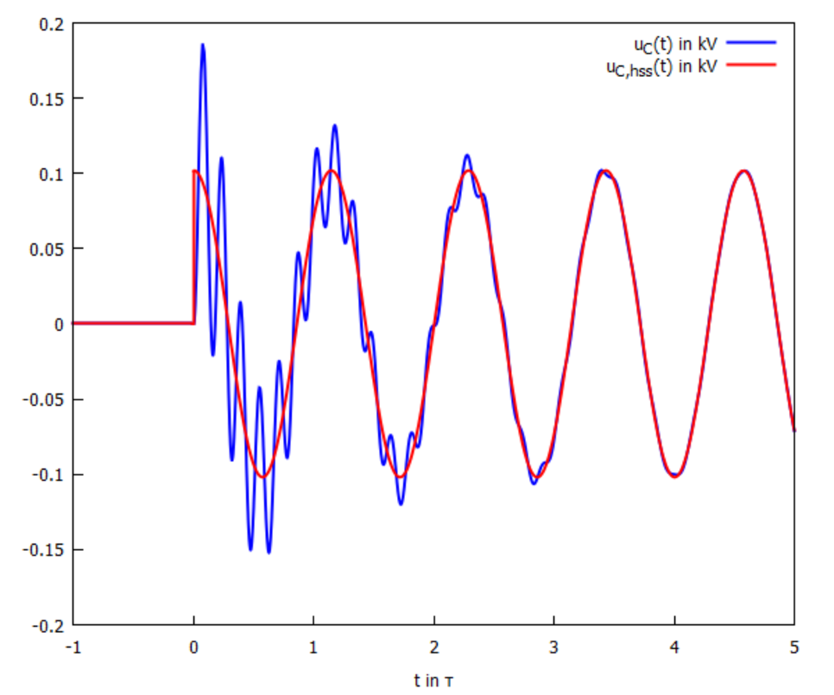
The network is supposed to be de-energized for t < 0 , so all initial conditions at t = 0 − vanish and u C ( t ) only depends on v s ( t ) . We calculate the transfer function via voltage divider: H ( s ) U c ( s ) : = V s ( s ) U c ( s ) = s C 1 + R + s L s C 1 = s 2 + s L R + C L 1 C L 1 = : ( s + α ) 2 + ω 2 ω 2 = H ( s ) V s ( s ) = ( s + α ) 2 + ω 2 ω 2 ⋅ s 2 + ω s 2 V 0 s ∣ ∣ ∣ ∣ ∣ s 0 = − 2 L R + 4 L 2 R 2 − C L 1 ≈ − 0 . 0 6 9 + 2 . 7 5 j = : − α + j ω Using two very general (and useful) formulae for inverse Laplace-Transforms with complex pole pairs, we directly get u C ( t ) : u C ( t ) = V 0 ∣ H ( j ω s ) ∣ cos ( ω s t + ∢ H ( j ω s ) ) + ω ∣ V s ( s 0 ) ∣ e − α t sin ( ω t + ∢ V s ( s 0 ) ) ≈ 0 . 1 0 2 cos ( 0 . 3 7 7 t − 0 . 0 0 6 9 7 ) + 0 . 1 0 2 e − 0 . 0 6 9 t sin ( 2 . 7 5 t + 4 . 6 9 ) The pure cosine in the first term describes the harmonic steady state (HSS) the circuit will converge to, while the decaying sine in the second term describes the effect of switching. Comparing angle frequencies, we find ω ≈ 7 . 3 ω s , so we expect a high frequency ringing around the HSS: With fixpoint iteration (or just zooming far into the graph), the first maximum is the global maximum and lies at
u
c
,
m
a
x
≈
0
.
1
8
7
k
V
. In volts, the answer is
1
8
7
Bonus: If we want to switch on the shunt capacitor at any point of the cosine wave, we need to add a phase-parameter to v s ( t ) : v s ( t ) = V 0 cos ( ω s t + ϕ ) ⇒ V s ( s ) = V 0 s 2 + ω s 2 s c ϕ − ω s s ϕ ∣ c ϕ : = cos ( ϕ ) , s ϕ : = sin ( ϕ ) The general formula for u C ( t ) above still holds - changing parameters are colored in red: u C ( t ) = V 0 ∣ H ( j ω s ) ∣ cos ( ω s t + ϕ + ∢ H ( j ω s ) ) + ω ∣ V s ( s 0 ) ∣ e − α t sin ( ω t + ∢ V s ( s 0 ) ) With the triangle inequality, we get an upper estimate for u C ( t ) that does not depend on ϕ : ∣ u C ( t ) ∣ ≤ ∣ V 0 H ( j ω s ) ∣ + ∣ V 0 ω ∣ ∣ s 0 2 + ω s 2 ∣ ∣ s 0 ∣ + ω s ≈ 2 . 2 ∣ V 0 ∣ Adding 10% tolerance, the capacitors should be rated for V m a x ≈ 2 . 5 ∣ V 0 ∣