Circuit for Practicing Numerical Solution
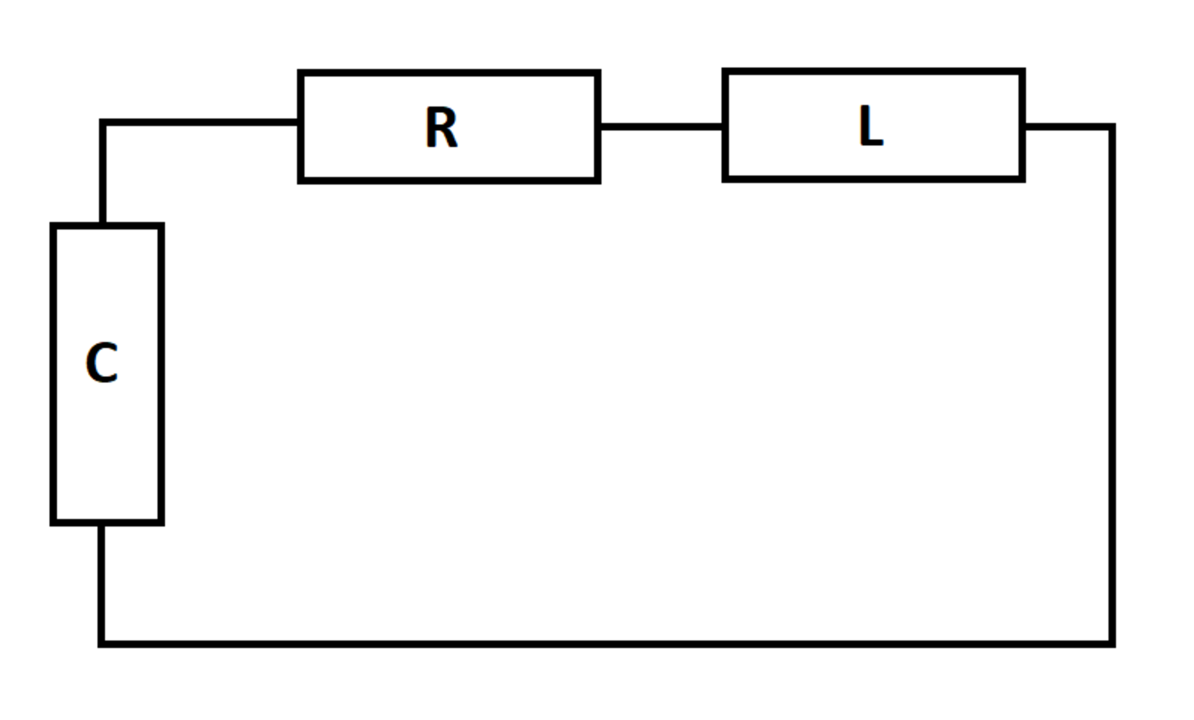
The series circuit shown below is solvable analytically, but I am posting this problem to give people an opportunity to try numerical solution methods on an easy practice circuit. The numerical techniques used to solve this problem apply equally well to more complex exercises.
The capacitor voltage is at time , and the inductor is de-energized at that time. Determine the value of the local current maximum which occurs between and .
Details and Assumptions:
1)
2)
3)
4)
The state variables are the capacitor voltage and the inductor current, which also happens to be the current flowing in all three elements. Write the time derivatives of the state variables in terms of the state variables themselves.
5)
The expected answer is a positive number

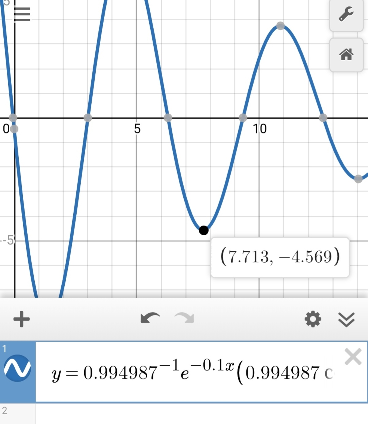
The answer is 4.587.
This section requires Javascript.
You are seeing this because something didn't load right. We suggest you, (a) try
refreshing the page, (b) enabling javascript if it is disabled on your browser and,
finally, (c)
loading the
non-javascript version of this page
. We're sorry about the hassle.


The state variables are the capacitor voltage V C and the inductor current I L . The basic equations are:
V L = L I ˙ L I C = C V ˙ C
Writing the left sides in terms of the state variables results in:
V C − R I L = L I ˙ L − I L = C V ˙ C
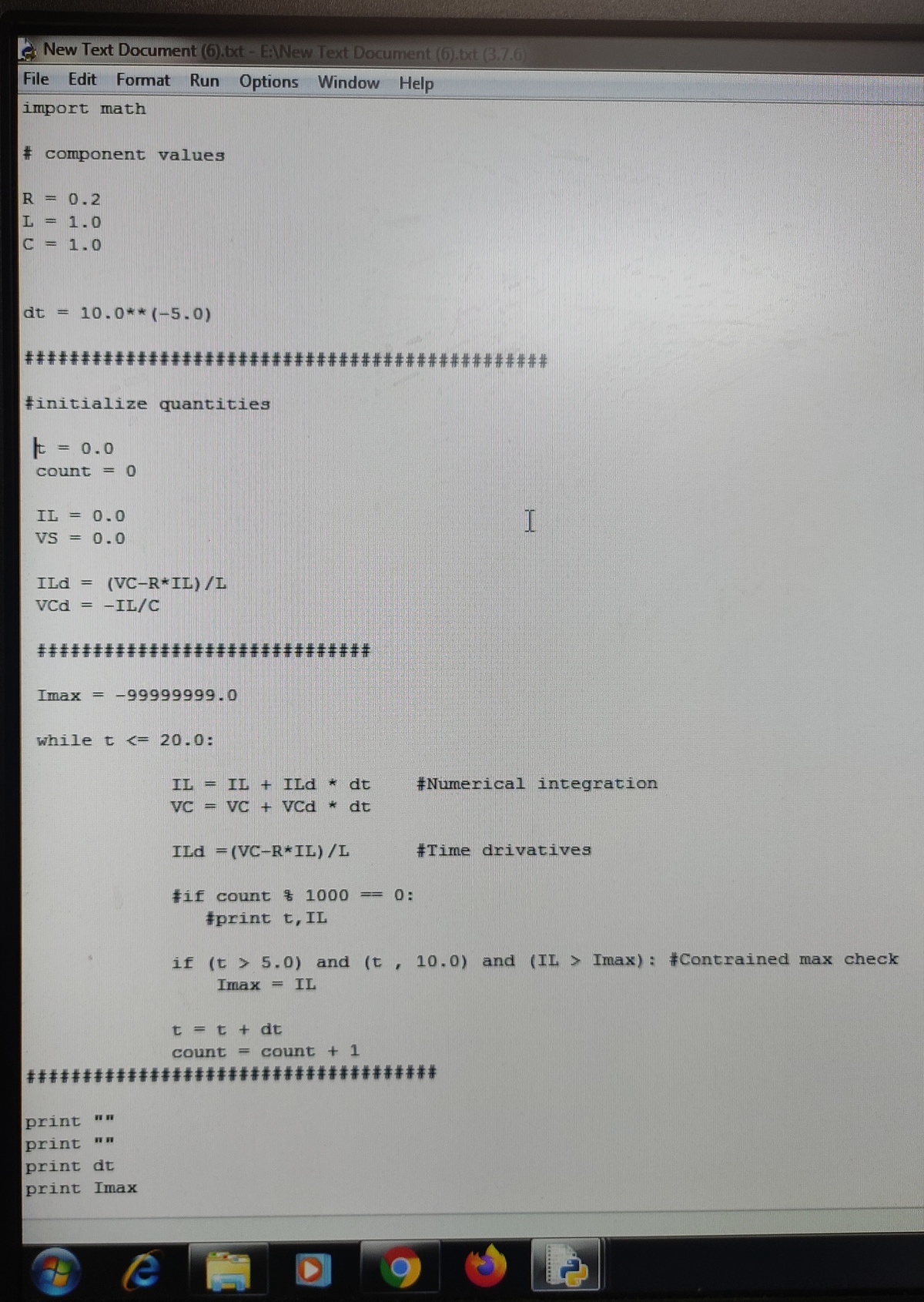
The plot of the current is included below, along with simulation code. Note that the damped sinusoidal behavior emerges from some very simple math operations.