Confused Charge
A particle of charge
q
is performing a uniform circular motion in a circular loop
(
L
1
)
of equation
L
1
:
(
x
−
3
)
2
+
(
y
−
2
)
2
=
1
,
z
=
0
A second loop is located at
L
2
:
x
2
+
y
2
=
1
,
z
=
1
 If the value of maximum and minimum flux produced by charge in loop
L
2
is
ϕ
M
a
x
and
ϕ
M
i
n
.
Evalute
ϕ
M
i
n
ϕ
M
a
x
=
?
The answer is 5.156.
This section requires Javascript.
You are seeing this because something didn't load right. We suggest you, (a) try
refreshing the page, (b) enabling javascript if it is disabled on your browser and,
finally, (c)
loading the
non-javascript version of this page
. We're sorry about the hassle.
1 solution
@Steven Chase Sir can you post a 2nd order RLC problem. Please
Log in to reply
I think I have posted many such problems, but I could probably do another. Do you want it to be AC steady state or transient?
Log in to reply
@Steven Chase DC current. Thanks
Log in to reply
@A Former Brilliant Member – Have you solved this yet?
https://brilliant.org/problems/circuit-for-practicing-numerical-solution/?ref_id=1584688
Log in to reply
@Steven Chase – @Steven Chase No, but i am solving it right now.
@Steven Chase Sir BTW your new problem (wavy) , can i solve it analytically?
Log in to reply
You might be able to form the integral that way. Whether or not Wolfram can solve it is another matter
Log in to reply
@Steven Chase Woot! I got the correct answer. I am posting solution right now
@Steven Chase
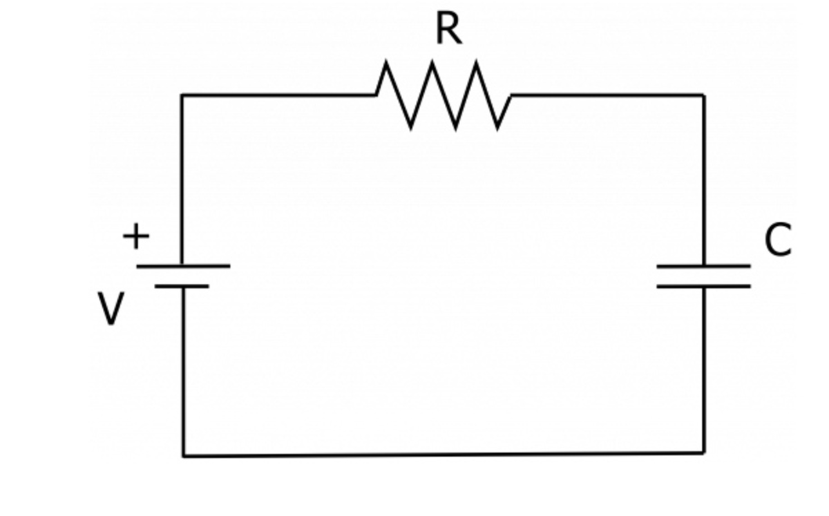
Sir I want to ask you a general doubt. Please can you help me.
I want to know that at
t
=
∞
why the voltage across the capacitor is equal to the voltage of battery?????
 .
.
In my opinion we should not allow Capacitor to do that. Because in the circuit resistance is also there and it will have some potential drop across it. Lets say at time
t
current
i
is flowing , so the potential drop across resistance is
i
R
, so the potential across the capacitor becomes
v
−
i
R
.
Please correct me I am wrong.
When I go to search this on internet everybody says that after long time capacitor develops the voltage across it equivalent to the battery. I am tired after hearing this several time.
Help.
Log in to reply
At t = ∞ , the capacitor voltage is equal to the source voltage, so the voltage across the resistor is zero, and there is no current.
Log in to reply
@Steven Chase But why that resistor allows capacitor to do that??
Log in to reply
@A Former Brilliant Member – When the capacitor voltage is less than the source voltage, there is a voltage across the resistor and a corresponding current through the resistor. This current gradually charges the capacitor. Eventually, the capacitor voltage reaches the source voltage, at which time the voltage difference across the resistor is zero. No current flows from then on, and the capacitor voltage remains equal to the source voltage.
This was a fun problem. Let the angular parameter for the z = 0 loop be θ 0 . Let the polar coordinates for the z = 1 loop be ( r 1 , θ 1 ) . For every value of θ 0 within a discretized range, calculate the flux through the upper loop and store the min and max values. Below is the simulation code, as well as a graph of the flux through loop 2 vs. θ 0 . The ratio comes out to be about 5 . 1 6 . I used a charge value q = 1 0 0