Equivalent resistance
What is the equivalent resistance between A and B?
This section requires Javascript.
You are seeing this because something didn't load right. We suggest you, (a) try
refreshing the page, (b) enabling javascript if it is disabled on your browser and,
finally, (c)
loading the
non-javascript version of this page
. We're sorry about the hassle.
7 solutions
Can you explain how the two diagrams are equivalent? I don't see how we can redraw it as you have
Log in to reply
Same, the equivalence of these diagrams is not obvious at all.
Log in to reply
Is not evident because he inverted the lower path. The more exact equivalence for the lower path would be one resistor in series with two parallel. From a logical thinking approach, it makes it unlogical but mathematically doesn't matter.
First, you have to realize that potential on the node between 2nd and 3rd resistor (on the line connecting A and B) is equivalent to potential at A (no resistor line). So you can start 'sliding' this node towards A (nothing is changing). Once you reach the first node next to A, you basically eliminate 'no resistor' line and this results in the desired diagram.
Assuming that the current is flowing from A to B just grab the end of the second resistor and place it on the head of the first resistor, which is very appropriate because the wire in between is a zero resistance wire and the points are at the same potential, giving you the desired equivalent circuit diagram.
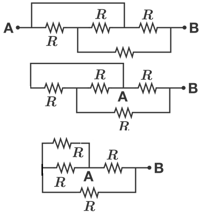 This is how we can redraw the circuit. First shift the point A and then make the resistors in parallel.
This is correct (and it took me a minute to realize it). There are three paths. If you number the resistors across the top of the original diagram r1, r2, r3 and the one on the bottom r4, I can explain it better. There are effectively three paths from A->B.
One path is straight through r3. Nothing will flow through r1 -> r2 because of the bridge above that path. The second flows through r1 -> r4 to B. The third flows across the bridge, back through r2 -> r4 to B. This is tricky because the direction of flow is right to left.
So you have current flowing in parallel through r1 and r2 into r4 and through to B. This is in parallel with the path r3. Which is what the second diagram shows (although labels would have helped). And that nets to the correct answer.
Log in to reply
No. Everyone seems to be missing the short circuit that allows the current to bypass the first two and bottom resistors. The actual resistance in that circuit, if measured by a meter, will be the equivalent of whatever value that last resistor has.
I've made a diagram showing various steps on how to convert the original diagram into this one, which should make it visually easier to understand.
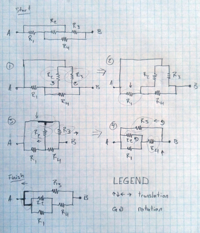
Can you elaborate on how you redrew the diagram please.
Log in to reply
Lol just use a delta-wye transformation ("https://en.wikipedia.org/wiki/Y-%CE%94transform") on the corners of the two ends of the short circuit and the point B, notice it is a deformed triangle, and you basically get 3R for the total resistance around the edges of the wye triangle because of the formula R(edge) = (R1(corner) R2(corner)+R2(corner) R3(corner)+R3(corner)*R1(corner))/R = (RR+RR+RR)/R = 3R^2/R = 3R, then if you deform the circuit diagram , the short circuit cancels out one of the (3R) resistors in parallel, to you essentially get (3R) paralleled with 2 sub-parallels (3R and R), so the total resistance ((1/(3R)+1/R)^-1^-1+1/(3R))^-1 = ( 1/(3R)+1/R+1/(3R)^(-1) = 1/(3R)+3/(3R)+1/(3R) = 5/(3R) ^-1 = 3R/5
 This is how we can redraw the circuit. First shift the point A and then make the resistors in parallel.
I see three paths. The top path goes through one resistor. Resistance = R. The middle path goes through 3 resistors. Resistance = 3R. The bottom path goes through 2 resistors. Resistance = 2R. The parallel resistance equation is 1/Req=1/R1+1/R2+1/R3+...+1/RN. So: 1/Req = 1/R + 1/(2R) + 1/(3R) Multiplying both sides by R we have: R/Req = 1 + 1/2 + 1/3 Multiplying both sides by 6 we have: 6R/Req = 6 + 3 + 2 = 11 Multiplying both sides by Req we have: 6R = 11 Req Thus: Req = 6/11 R which is not one of the answers. Am I wrong? Where did I go wrong?
Log in to reply
use a delta-wye transformation ("https://en.wikipedia.org/wiki/Y-%CE%94transform") on the corners of the two ends of the short circuit and the point B, notice it converts the shape from a deformed wye "Y" shape to a deformed triangle, and you basically get 3R for the total resistance around the edges of the wye triangle because of the formula R(edge) = (R1(corner) R2(corner)+R2(corner) R3(corner)+R3(corner)*R1(corner))/R = (RR+RR+RR)/R = 3R^2/R = 3R, then if you deform the circuit diagram , the short circuit cancels out one of the (3R) resistors in parallel, to you essentially get (3R) paralleled with 2 sub-parallels (3R and R), so the total resistance ((1/(3R)+1/R)^-1^-1+1/(3R))^-1 = ( 1/(3R)+1/R+1/(3R)^(-1) = 1/(3R)+3/(3R)+1/(3R) = 5/(3R) ^-1 = 3R/5
Lol just use a delta-wye transformation on the corners of the two ends of the short circuit and the point B, notice it is a deformed triangle, and you basically get 3R for the total resistance around the edges of the wye triangle because of the formula R _ (edge) = (R1 _ (corner) * R2 _ (corner)+R2 (corner) * R3 (corner)+R3 (corner) * R1 (corner))/R = (R * R+R * R+R * R)/R = 3 * R^2/R = 3 * R, then if you deform the circuit diagram, the short circuit cancels out one of the (3*R) resistors in parallel, to you essentially get (3 * R) paralleled with 2 sub-parallels (3 * R and R), so the total resistance ((1/(3R)+1/R)^-1^-1+1/(3R))^-1 = ( 1/(3R)+1/R+1/(3R)^(-1) = 1/(3R)+3/(3R)+1/(3R) = 5/(3R) ^-1 = 3R/5
The correct answer would be R. path of least resistance always applies.
Log in to reply
But (3/5)R is a value of resistance that is lower than R as 3/5 < 1. Therefore, (3/5)R is the path of least resistance, and the correct answer. However, I still don't understand how the equivalent diagram drawn above was produced from the original diagram...
Log in to reply
I tried to explain that in my previous response. If it's not clear, I can post up a drawing but I think it should make sense. Let me know.
Log in to reply
@Dan Lubart – the drawing with the evolution to the stages explains it all
That's not true, Philip. Two resistors in parallel offer lower overall resistance than either resistor by itself does. Current doesn't choose one path over another but uses both in inverse proportion to the amount of resistance each offers. The formula is 1/Rt = 1/R1 + 1/R2 ... + 1/Rn.
 This is how we can redraw the circuit. First shift the point A and then make the resistors in parallel.
Suppose each resistor was 1 Ω and we applied a 1 V source from A to B . We immediately know almost all of the voltages in the circuit, as shown.
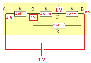
We don't know the voltage at C . Use Kirchoff's Current Law to find this voltage.
1 V C − 1 + 1 V C − 0 + 1 V C − 1 = 0 3 V C = 2 V C = 3 2
Find the current flowing into A or out of B . It's easy to calculate the current out of B .
I o u t = 1 3 2 − 0 + 1 1 − 0 = 3 5
The total resistance is therefore:
R t o t a l = I o u t V s o u r c e = 3 5 1 = 5 3
Of course, this would scale the same way regardless of the value of each resistance.
the point is the same as D , so the resistor AC and CD are parallel , Req1 = R //R , the resistor B is serial with Req1 so Req2 = Req1 + R = R//R + R , finally the resistor CB is parallel with Req2 and as a result : Req = ((R//R)+R)//R
Log in to reply
This could be a solution, rather than a comment
Going by first principles -
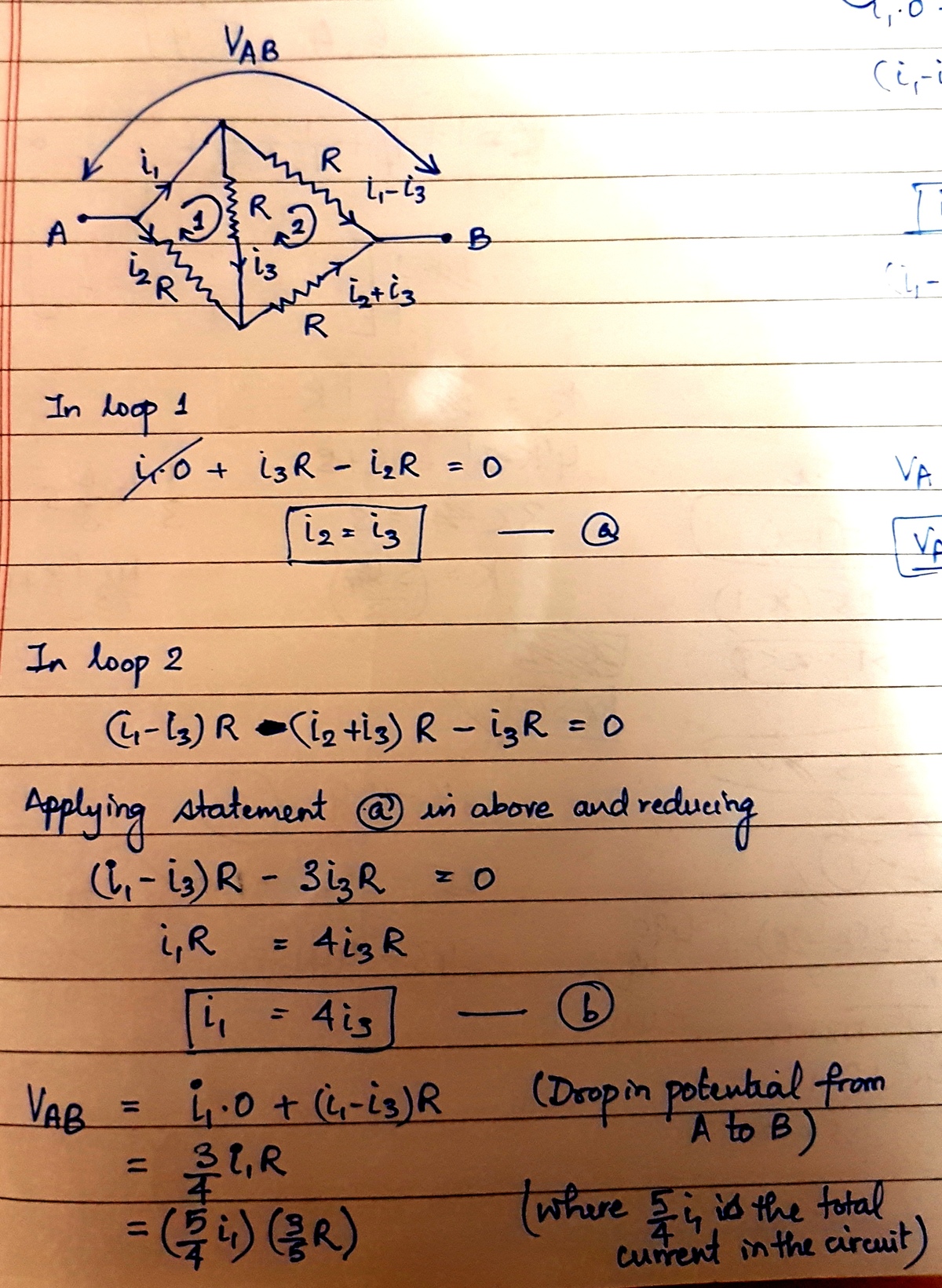
Consider the circuit as given in the image.
Total current in the circuit is (i1 + i2) getting distributed in the two arms. Further, i3 flows through the central arm. The potential drop in the loops 1 and 2 will be zero. The potential drop from A to B will be total current (i1 +i2)*effective resistance (3/5R). Hope this helps.
Process of elimination.
2 R would require an equivalent circuit so that there are two equivalent resistances in parallel R between A and B. Since A is shunted across R to B there is no equivalent resistance network which will allow the Y network of R resistors to also be R , so it can be eliminated. It's worth pointing out that another resistor R could be added to the circuit to get that result, but not with those 3 configured they way they are.
5 3 R we skip.
R isn't a reasonable solution because there's for sure a divider between the A → R → B path, so the entire resistance network it must be less than R .
4 R isn't a reasonable solution for the same reason. We know there's a divider so it must be less than R .
A quick spot check just says that the resistance can't be ≥ R and 2 R seems equally as unlikely.
I thought that if you bridge a resistor, it is as if it does not exist, so the first two resistors are bridged and current takes the path of list resistance, so I eliminated them from the circuit.. At least that is what I have experienced in real life.
Log in to reply
Indeed in real life applications the current would take the path of least resistance, however as there are no values specified we have no way of telling which way it would be and as such it should be treated as a logical /mathametical problem rather than an electrical one, that being said, I follwed the same logic you did ;-)
Log in to reply
The problem involving resistance with the symbols given is an electrical problem. The laws of electricity must be applied. At least that is my opinion. The problem as stated is ambiguous.
Log in to reply
@Sean Forbush – Both a mathematical and an electrical analysis of this circuit give exactly the same result. The problem is not ambiguous at all.
The current won't exclusively take one path when multiple routes exist, it will be shared over all of the available paths. If the current only took one path, it would never be possible to place any components in parallel because only one would be powered - imagine a simple torch with two bulbs where only one could be lit.
What you'd have to do is look at the current flow. Looking at Steven Chase's solution shows how you would need to do this. Notice that nodes V A and V D have the same voltage. V A is not shorted with V B . What this means is that the current is divided. In a series the resistance is added together. In parallel, it is divided. R t 1 = R 1 1 + R 2 1 + … + R n 1 . That in itself may not be intuitive, so think about it as though you're adding more potential path ways. If you go back and solve the voltages at each node, you can use V = I R to see the relationship of the voltage drops and if you build this circuit, you will see that it matches practically, not just theoretically.
I had initially thought of the same thing which would probably have been the most common mistake but both of us have missed a very important point that in between the resistors 1 and 2 there is a third resistor which causes a potential difference across resistor 1 (+ve) and across resistor 2 (-ve). Here is a link to a simulation to show you what I am talking about : http://tinyurl.com/yb23qa4n
The diagram is redrawn by giving letters. In new diagram, it is easier to see series-parallel resitances. The result is 3/5 R.
I see it as finding the number of shortest routes the current can take, adding up the resistances together for each path, take the inverse of it, then sum of all the inverse values, before inversing the sum of inverse values.
the solution is 3R/5 the point is the same as D , so the resistor AC and CD are parallel , Req1 = R //R , the resistor B is serial with Req1 so Req2 = Req1 + R = R//R + R , finally the resistor CB is parallel with Req2 and as a result : Req = ((R//R)+R)//R
The diagram may be redrawn as below: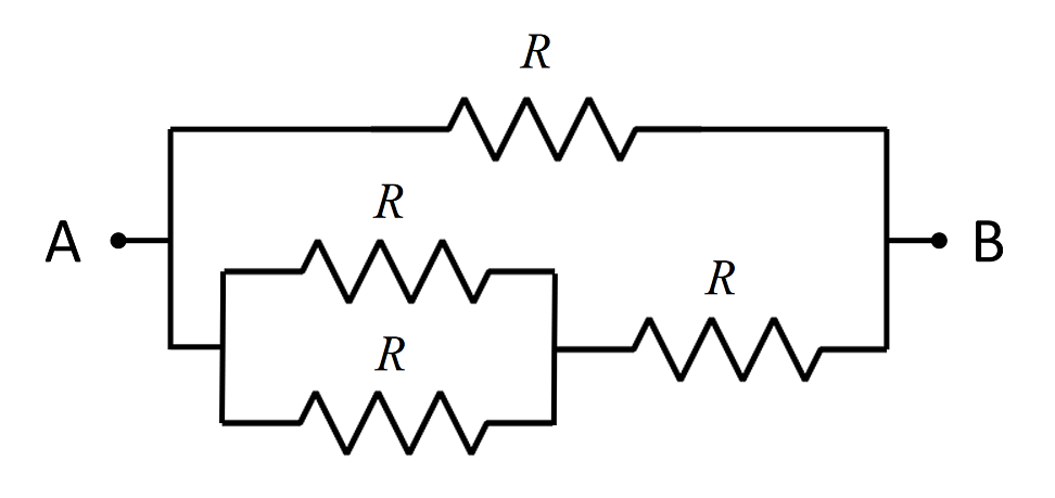 The resistance of two resistors
R
wired in parallel is
2
1
R
.
So the resistance of the lower half of the circuit is R + 2 1 R = 2 3 R
The resistance between A and B is then given by:
R 1 + 3 R 2 1 = 5 3 R