How to switch on the bulb?
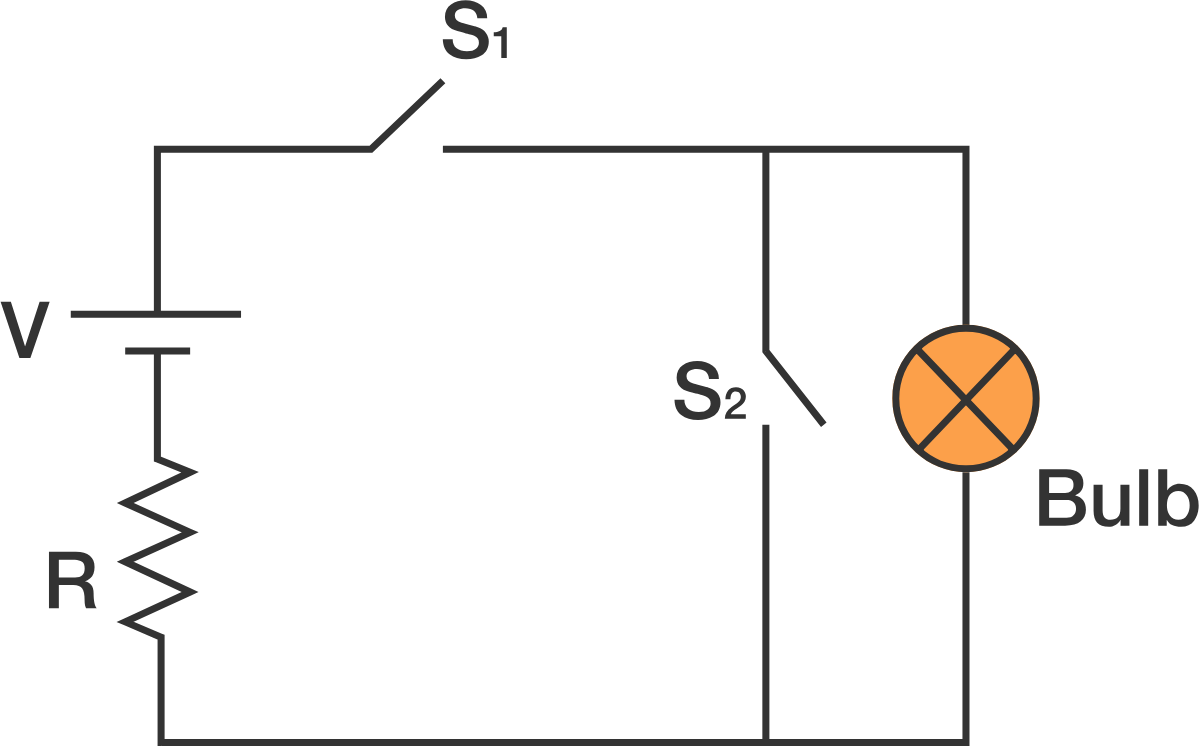
A filament bulb is connected with a battery, a resistor, and two switches S 1 and S 2 , as shown in the diagram above. For which combination of the switches will the bulb glow?
Assume the connecting wires have negligible resistance.
This section requires Javascript.
You are seeing this because something didn't load right. We suggest you, (a) try
refreshing the page, (b) enabling javascript if it is disabled on your browser and,
finally, (c)
loading the
non-javascript version of this page
. We're sorry about the hassle.
6 solutions
There is a resistor shown in the circuit. With S1 closed, the resistance of the circuit with the bulb is R + the resistance of the bulb. With S2 closed, the current that will flow through the circuit without the bulb is V/R, and the current that will flow through the circuit with the bulb is V/(R+bulb). The bulb will light, but more dimly. The answer given is incorrect.
Log in to reply
the wires having no resistance effectively sends all the current through the S2 branch when the S2 switch is closed
the bulb has resistance, say as little as 6 ohms in a flashlight bulb there would be so little current going through the bulb side of the parallel circuit that the bulb would not glow
V/R (if R is really 0 is undefined mathematically) if I assume that bulb resistance is 6 ohm and the S2 R then I must calculate how thin, wide, and long and at what temp a circuit board trace wire would have to be to produce any significant resistance
I can get almost 4 ohms of resistance in a 1mil x1mil x6inch copper trace at 20C
If I lengthen the 1mil x 1mil trace wire to 9 inches I can get almost the equivalent resistance that the bulb has
BUT the conditions presented in the problem assume a wire that effectively does not present the kind of resistances that a trace on a circuit board does
https://www.allaboutcircuits.com/tools/trace-resistance-calculator/ https://www.allaboutcircuits.com/tools/parallel-resistance-calculator/
so in the example presented, the S2 circuit resistance is so low that it keeps the bulb from glowing
thanks for making me think about this because in a world of circuit boards the calculations would be quite important @
Log in to reply
You have still to address the resistance R that is explicitly shown in the circuit. We are not talking about the resistance of the wires, which is stated as zero. There is no short circuit in the loop with switch S2 because there is a resistance R explicitly shown in that circuit. There is no basis for the statement that the S2 circuit resistance is so low that it keeps the bulb from glowing. The resistance of that circuit is R. The resistance of the circuit with the bulb is R+ bulb.
Log in to reply
@Royce Reinecke – @Royce Reinecke Let's call the resistance of the wire/switch Ω S 2 and the resistance of the resistor Ω R . If S 2 is closed then it's in parallel combination with the lightbulb and the current splits according to I S 2 I R = Ω R + Ω S 2 Ω R = Ω R + Ω S 2 Ω S 2 Since we assume that Ω S 2 = 0 , this means that the current flowing down the light bulb branch ( I R ) is also zero.
Similarly, since they're in parallel combination, the resistance of the S 2 + light bulb branch is Ω S 2 Ω R / ( Ω S 2 + Ω R ) which is also zero. Thus the total resistance of the circuit is given by the resistor next to the voltage source.
Log in to reply
@Josh Silverman – Correct! The issue is not the resistance of the wire, if the light bulb, or of the switch. The issue is the resistance explicitly called out in the problem. If the resistance of the light bulb is zero, or very small in comparison to resistance R, the current flowing down both paths is divided equally down both paths with switch S2 closed. The bulb will light with switch S2 open, and half as brightly with S2 closed, but will light in both cases.
Log in to reply
@Royce Reinecke – The bulbs generally have large resistances. To be more explicit I've updated the problem statement and mentioned filament bulb instead of a bulb.
@Royce Reinecke – Not if we accept "zero resistance" wires & switches - mathematically all the current will still go down the S2 path and not the light bulb path. Half as bright also implies that the S2 path has the same resistance as the light bulb path.
This is almost correct, but there will theoretically be some flow through the bulb however low. So, l the disagree with the answer in the app.
Log in to reply
Ahh crap it did say negligible resistance. Okay I withdraw my comment.
Log in to reply
Can the bulb glow for any current?
If the current is very small then the temperature of the bulb won't shoot up high enough to make it glow.
doesn't closing switch 2 provides a short circuit, (zero resistance) making the bulb resistance essentially infinite (versus zero) with no current flow in that branch??
Log in to reply
Closing switch 2 does not provide a short circuit, because their is a resistance R shown in the circuit next to the Voltage source. A short circuit would only exist if there were no resistance R shown in the circuit.
Log in to reply
Yes, closing switch 2 shorts out the light bulb - it doesn't not short out the whole circuit.
I figured the globe would glow, but would be diminished as only half the current would flow through the globe.. that would only work if the globe had no resistance.. which clearly can't be true because without resistance it wouldnt function I suspect the whole point to this problem is to expose this kind of incorrect thinking ..
Log in to reply
Can you think of a reason that the current would split in half?
Log in to reply
Just using the current analogy, if these were channels and water, in my imagination the water would initially flow equally along both channels if there were no significant resistance on the longer channel. Of course if I'd thought about the light as a resistor which is equivalent to a partial blockage or incline in the channel, my mental model says that more water would flow through the channel without resistance (blockage / incline). Its entirely possible that the electrical current / water current analogy simply doesn't extend this far, or that my mental model of what would happen with water is simply wrong. Part of me wants to run an experiment to see how far the analogy holds and to compare that against what might happen in an electrical circuit like the one in the diagram with reasonably high voltages (water pressure) and gradually increase resistance across one of the channels. I just wish I had the time to tinker that much :-)
Log in to reply
@John Martin – The analogy does hold up pretty well actually. If you have an ideal channel and make it wider, that does indeed lower its "resistance" to a given flow.
The only issue here is that to get the channel for S 2 right you'd have to make it infinitely wide (or give it a length of zero). If you want to learn more, look up the Hagen–Poiseuille relation.
Log in to reply
@Josh Silverman – Thanks Josh .. now I'm getting my head around Newtonian fluids and plugging formulae into excel (might look at Wolfram alpha too to see if that works better for this kind of thing) .. I've learned something new which is nice :-)
effective resistance can't be Zero, bulb depending on its resistance will glow may be with very low intensity, some current however low it may be will flow through the bulb, shouldn't it be?
Log in to reply
What is your argument for current flowing to the bulb?
The problem states the wires have no resistance, however, the switch would have resistance. Therefore, since the resistance across the current path through S2 is not 0, the bulb would draw current to some extent.
I believe you're slightly mislabelling things here. You are correct with S1. But if S2 is closed the bulbs resistance doesn't change, the combined parallel resistance in that part of the circuit changes. The bulb still has a much higher resistance than the zero resistance offered by the closed S2 switch, and as such (in this specific case) all the current would go through the switch and none through the light bulb (and then through the resistor). If you're changing the resistance of the bulb, you're changing the question. ;) Again at the end you're correct, S2 has to be open for the bulb to light.
Royce Reinecke said it true. The correct answer should be that S1 should remain closed, but the state of S1 is irrelevant.
Relevant wiki: Simple Circuits
option-1... if both switches are closed, then suddenly the effective resistance become 0 and causes a short circuit.
option-2....a battery only works if among 2 switches, both works oppositely and electricity will find the shortest distance.[the bulb will glow then]
option-3...if 1 of the switches is irrelevant, then the system of the Daniel cell is not fulfilled and it causes a short circuit.
therefore, option-2 is correct.
option-1, there is a resistor just after the battery, so the resistance wouldn't become 0.
Log in to reply
oh yes.but the effective resistance would be 0 if both switches are closed.as no electricity is passing there is no work for the resistor just after the battery.
Log in to reply
I agree with Kim. There is a resistor in series with the battery, so there can't be a short circuit. However I see your point. No current would pass through the bulb if S 2 is closed because it is in parallel with a wire with zero resistance.
Log in to reply
@Pranshu Gaba – If both the switches are closed then the bulb will be short circuited and not the battery.
Relevant wiki: Kirchoff's Voltage Law (closed loops)
One way to see that the solution is not S1 and S2 being closed, is to use the loop rule. If we go around any loop of closed circuit (say clockwise), the sum of the voltage drops should be equal to the sum of the voltage increases. In the case where S1 and S2 are closed, we get a skinny rectangular loop with S2 and the lightbulb. If we go around this loop clockwise, supposing there is some positive voltage drop across the lightbulb, we will find no counteracting voltage increases, contradictory to the loop rule. Therefore there must be no voltage drop across the lightbulb i.e. no light!
While I appreciate this circuit and solution works in theory, in practice a circuit like this is not likely to be built. IMHO this is useful as a thought experiment only.
That's a crisp solution.
doesn't S2 have some resistance
You ignored the resistance shown in the circuit.
Electricity prefers to take the path of least resistance in a circuit whenever "given an option" of flowing down two different forks in the path of electric flow. When switch S2 is closed (allowing electricty to flow), then electricity preferentially flows through S2 to reach the end of the circuit, since the resistance of that pathway is essentially 0 and therefore infinitely easier to traverse compared to whatever resistance the bulb provides. This is what a "short circuit" looks like in electric diagrams.
it wpould not be a short circuit because of resistance R
Closing S1 completes the circuit,however,closing S2 creates a short circuit , where all the current flows through S2 (as potential drop across the bulb is zero). Hence option B is correct.
If S1 closed then path is completed and Bulb will glow. If S2 closed then path be short-circuit and Bulb will not glow therefore S1 closed and S2 open
Relevant wiki: Simple Circuits
Switch 1's closure is essential to driving any current from the battery towards the bulb. If Switch 2 is also closed, then the effective resistance of the bulb becomes zero due to its parallel arrangement with a short circuit. Therefore, Switch 2 must remain open in order to illuminate the bulb.