Imbalance Puzzle a detailed version inspired by Chung Kevin
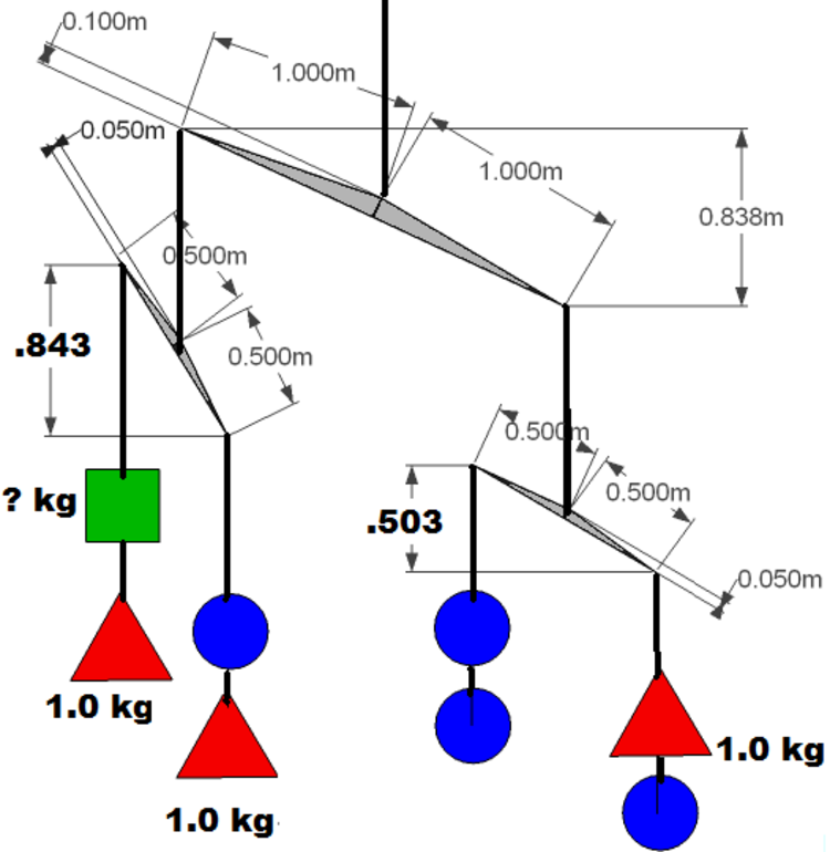
 The above shows how a mobile will be balanced when left to hang. The tilt of each beam is shown on the diagram.
What is the mass of the green square?
This section requires Javascript.
You are seeing this because something didn't load right. We suggest you, (a) try
refreshing the page, (b) enabling javascript if it is disabled on your browser and,
finally, (c)
loading the
non-javascript version of this page
. We're sorry about the hassle.
1 solution
Would your solution work if the arms were linear such as a wire from a clothes hanger and not squat triangles as you have shown in your problem?
Log in to reply
The point to consider is that in order for any balance beam to reach an equilibrium position at some angle of displacement from horizontal it must have a vertical component to the beam. ie the center pivot point must be above the outer weight connection points.
scenario #1 If the clothes hanger wire was bent but rigid (no flexing) so that the points where the three forces are connected maintain the same relative position to each other the system would balance as described. In this system as the beam rotates the fulcrum point (in the center) effectively move towards the side of the beam that is moving downward (relative to the horizontal center of the beam). This is do to the vertical component of the beam no longer being totally vertical.
It would make no difference what the shape of the wire was ,curved, sharp bends at each end, a kink in the middle or some random balanced shape. All that counts is the vertical and horizontal distances that are fixed between the fulcrum and the ends.
2
If the clothes hanger wire was straight and remained straight the system would not balance at all. In that case the side of the beam with the greater moment would hang vertically downward and the side with the lesser moment would point straight upward. This is assuming that there is no interference or contact between any of the hanging weights or connecting strings as they moved into the same vertical plane. There is nothing in that system to limit the rotation of the beam it would just move to the position of the heaviest side down.
3
If the clothes hanger wire was straight but is flexing elastically under the load placed on it by the hanging weights this become a much more evolved problem. We would require some information about the elastic characteristics of the beam. We would have to calculate the amount of flex in the beam with respect to the torque load placed on it by the weights. The beam would begin tilted do to the uneven moments placed on it by the weights. As it did the moment on the beam becomes smaller resulting in less torque, less flex. because the horizontal distance from the weights to the fulcrum gets smaller. So as the beam tilted it would also become straighter. Depending on the elastic characteristics of the beam and the load placed on it, the beam may balance at some angle. To actually calculate that angle would require more information about the elastic properties of the beam. It is also possible that this system would end up as a straight beam hanging in a vertical position with the weights hanging from both ends.
Log in to reply
Thanks, Darryl. I had no previous experience with this before and I was baffled and curious about the physics involved. All we had familiarity with was a balanced situation made of unequal masses and unequal weight arms. However I did an experiment and got some unusual photos. Can you justify these?
 For Darryl
Log in to reply
@Guiseppi Butel – It is a bit difficult to see details of what is going on from the photos but I can speculate on the results you are seeing.
If the wire you are using is not perfectly straight it will naturally rotate,,about its diameter (roll), to the position where the center of gravity is the lowest it can possibly be. That natural position of balance for the rod by itself will result in the center string attachment location being directly above the center of gravity of that balancing rod. It is more or less the definition of balancing ie keeping the center of gravity above or below the support point. Above is difficult to maintain because any tiny movement away from that position will result in gravity contributing to that movement and continuing it. The center of mass below the support point is very natural because any movement away from that position is resisted by gravity which will produce a force to move the system back . I suspect the rod you are using as a beam is not truly straight.
If the pivot point of the rod is truly at the center of gravity for the rod it will never move when suspended from that center of gravity point. It will just hang at any position that you place it. The only reason that your rod balances at any angle, horizontal or otherwise, is because it is moving to a position where the center of gravity is directly below the pivot point on the center string.
The second point is where the (string) connections are free to pivot with respect to each other. Are the three points at witch the strings are free to pivot truly in a straight line? If the three point are in a straight line and remain in a straight line as the beam is rotated then the ratio of relative moments on each side of the beam can never change with the angle the beam is sitting. We could say that the side of the beam with the greatest moment will always maintain the greatest moment and will therefor end up pointing straight down. I suspect that the string attachment point that you have on your system have a vertical component to them (at the starting point of horizontal attachment) . ie as the rod tilts the string do not hang from the same exact point as they did original. even the width of the rod itself would be a subtitle factor. To truly build a beam that eliminates this factor would require careful design, something like three friction-less bearings carefully mounted in a straight line on a beam.
Log in to reply
@Darryl Dennis – After I read your first explanation I think I figured how I obtained a slanted equilibrium state with a straight arm and with the pivot point in the center. I had attached the main supporting thread with some tape that extended partly up the thread. This provided some vertical force when one side angled downward.
Log in to reply
@Guiseppi Butel – Yes! all balancing beam will have a vertical component in order to establish a equilibrium. The reason I had indicated that particular shape for the beams in the original problem was an attempt, by me, to make it clear what the vertical component was for the beams in the problem. In many real life systems it may not be totally clear where the pivot points are or what the actual displacement distances between points may be. As the system moves, changes tilt angle, the pivot points may move relative to each other because of the way the system is constructed.
To be more precise it should also by recognized that the mass of the beams will have and effect on the answer for this problem. The solution assumes that the mass of the beams is zero or at least negligible with respect to the mass of the hanging weights. It would add some complexity to the problem if the mass of the beams was given and it was stipulated that the beams where cut from a flat constant density material. In that case we would have to determine the location of the center of mass of each beam and determine the vertical displacement distances from the fulcrums pivot points. In reality it would take some small moment on each beam to tilt it, if it has mass.
The solution is not so much a method to determine a answer for this problem, but is a recognition that any balancing object will have exactly equal moments on each side of the balancing point, and as a beam is tilted the relative location of the center fulcrum is displaced towards the side that is moving downward which results in the balancing point.
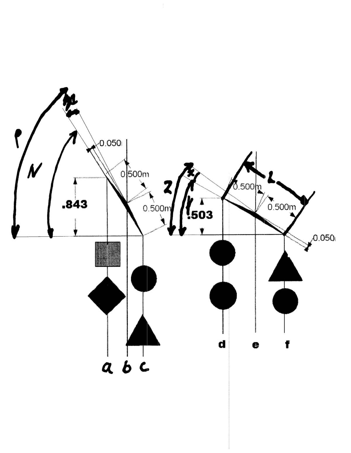
We only need to consider two of the beams. I will use the two lower beams.
Calculate beam length 2 × ( . 5 2 − . 0 5 2 ) = 0 . 9 9 5 m Calculate beams reach vs drop angle X X = s i n ( . 0 5 / . 5 ) = 5 . 7 d e g Consider right beam Calculate angle of displacement of the beam produced by hanging weights Y Y = S i n ( . 5 0 3 / . 9 9 5 ) = 3 0 . 4 d e g Calculate right distance from fulcrum to force produced by weights hanging on beam ef Right side- -Distance = ef e f = 0 . 5 ( c o s ( 3 0 . 4 + 5 . 7 ) ) = 0 . 4 0 4 m Horizontal distance between ends – Distance =fd d f = t a n ( 3 0 . 4 ) 0 . 5 0 3 = . 8 5 7 m Left side – distance = .de d e = 8 5 7 − . 4 0 4 = 0 . 4 5 3 m Calculate mass of blue circle, Mb, using sum of moments about pivot point 0 . 4 5 3 × 2 × M b = 0 . 4 0 4 × ( M b + 1 ) M b = . 8 k g Consider left side beam calculate angle of displacement of of the beam S i n ( . 8 4 3 / . 9 9 5 ) = N = 5 7 . 9 d e g Right side -Distance =bc b c = 0 . 5 ( c o s ( 5 7 . 9 + 5 . 7 ) ) = 0 . 2 2 2 m Horizontal distance between ends= ac a c = t a n ( 5 7 . 9 ) . 8 4 3 = . 5 2 9 m Left side – distance =ab a b = . 5 2 9 − . 2 2 2 = . . 3 0 7 Calculate mass of green square= Mg _ . 3 0 7 × ( M g + 1 ) = . 2 2 2 × ( 1 + . 8 ) Mass of the green square M g = 0 . 3 k g