Induced Voltage in a Rotating Rod
Consider a conducting rod of unit length hinged at the origin of the X-Y plane. It can freely rotate about the origin and the motion of the rod is confined to the X-Y plane. There is an ambient magnetic field present throughout space and its flux density is specified as:
B = e − x 2 + y 2 k ^
The rod rotates about the origin with a constant angular speed of ω = 1 . Compute the magnitude of the voltage induced across the fixed and free end of the rod.
Note:
-
The unit vector along the Z direction is k ^
-
e ≈ 2 . 7 1 8 is the Euler's number.
The answer is 0.264241.
This section requires Javascript.
You are seeing this because something didn't load right. We suggest you, (a) try
refreshing the page, (b) enabling javascript if it is disabled on your browser and,
finally, (c)
loading the
non-javascript version of this page
. We're sorry about the hassle.
2 solutions
Here are some conceptual quandries that I have been wrestling with after seeing this problem
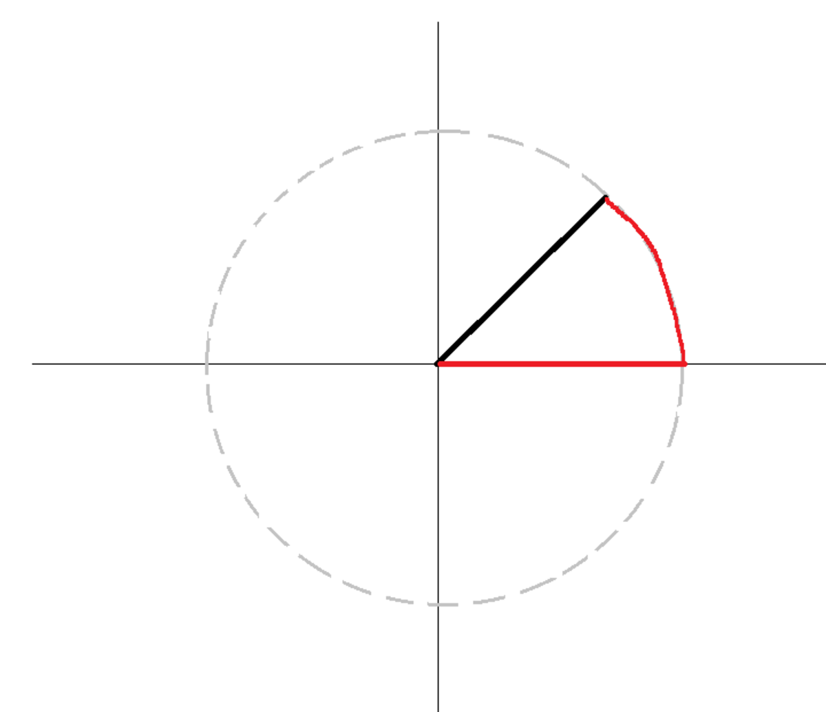
From the integral form of Faraday's law, we know that the voltage induced in the closed wedge-shaped loop is 2 e − 2 . Part of the loop (black) is the rod, and part of the loop (red) is free space. This problem expects that all of the voltage is across the rod, and that none of it is across the free space path.
∫ rod E ⋅ d ℓ = 2 e − 2 ∫ free space E ⋅ d ℓ = 0
But how do we justify this expectation?
Take another example of an electric circuit in which you have a voltage source connected across a series combination of a very large resistor and a very small resistor. The great majority of the source voltage will drop over the large resistor. Going back to the induction problem, the free space path seems to be analagous to the large resistor and the rod is analogous to the small resistor.
Another conceptual problem. What if we get rid of the physical rod entirely and just have an imaginary moving boundary line which determines the size of the wedge? Given that the magnetics are static in time, is it reasonable to talk about voltages being induced in this situation? As we have seen before, the loops and surfaces dealt with by Maxwell's laws need not be physical or made of matter. They can be purely spatial/mathematical objects.
I think that throughout all free space, the line integral taken over any closed loop will evaluate to zero. Consider:
∮ C E ⋅ d l = − ∫ S ∂ t ∂ B ⋅ d S
Since the magnetic field is time independent:
⟹ ∮ C E ⋅ d l = 0
Now let us look at the rod only. The way I like to think of induced voltages in moving conducting bodies is as such. At any point on the rod, consider an arbitrary free electron. This electron experiences a magnetic force F = q V × B . The force on this arbitrary electron will be radially inward in direction, in the given case of the problem. So over time, there is an accumulation of electrons near the fixed end and a scarcity of them near the free end. This is what gives rise to the potential difference across the rod ends.
The way I see it, the the voltage induced throughout free space is zero owing to Maxwell's equations and that has nothing to do with the voltages across the rod ends. Another argument to consider here is that if the rod is nonconducting, there would be no voltage induced as non-conductors have a scarcity of free electrons. In that case, the induced voltages in free space and and the rod would be zero.
I have not thought very carefully about the additional examples that you provided, keeping in mind the above context, but I will dwell on them later.
Log in to reply
@Karan Chatrath
Now i have just seen your report
Sir Very very very sorry for the late reply,i have corrected my new problem. Apologies for the error.
I was very busy in solving calculus.
Log in to reply
No problem and thank you for re-posting. I will share my solution when I can
Log in to reply
@Karan Chatrath – @Karan Chatrath Sir can you solve this. Find the percentage error in R e q u i v a l e n t when two resistance R 1 and R 2 are connected in parallel. R 1 = ( 5 + 0 . 2 ) Ω R 1 = ( 5 − 0 . 2 ) Ω R 2 = ( 1 0 + 0 . 1 ) Ω R 2 = ( 1 0 − 0 . 1 ) Ω I want to write this 2 resistance in that type of form +and- both up and down, but I don't know that .
I like your explanation in terms of a magnetic force polarizing a rod. With regard to the integral form of Faraday's law, it seems there are two possibilities.
1) The integral form of Faraday's law does not apply to time-varying loop geometries (only to static loops). I doubt this, because the "electromechanics" problems and problems like it assume that it can be applied this way.
2) It does apply to time-varying loop geometries, but in that case, you can't take the time derivative inside the integral. It is fairly obvious that for a varying loop geometry, the rate of change of flux is nonzero even though the B-field is static.
Log in to reply
I think the second possibility is valid. So essentially:
∮ C E ⋅ d l = − d t d ( ∫ S B ⋅ d S )
is a more general statement of Faraday's law which also accounts for time-varying geometries as well as time-varying flux densities.
Log in to reply
It's not the thinking, it's the truth. Induced E. M. F. is the negative rate of change of magnetic flux linked with a closed loop : Induced E. M. F. = − d t d Φ m a g = − d t d ∫ ∫ B . d S = − ∫ ∫ ( ∂ t ∂ B . d S + B . d ( ∂ t ∂ S ) ) .
@Steven Chase are you posting any new question today. Please tell otherwise I have to keep checking.
Log in to reply
I don't think I will
Log in to reply
@Steven Chase Can you post a second order RLC problem. I like that problem very much please upload one today. As you are very smart it will take you few minutes only.
F u n P r o b l e m
I will be happy if you increase the level. Take any arbitrary point in the region x 2 + y 2 ≤ 1
As ( r cos θ , r sin θ )
By going a distance r take d r
e i n d u c e d = B v l d e i n d u c e d = B r ω d r ∫ d e i n d u c e d = ∫ 0 r e − r r d r = e e − 2
Use integration by parts to evaluate the integral e i n d u c e d = 0 . 2 6 4 2 4 1