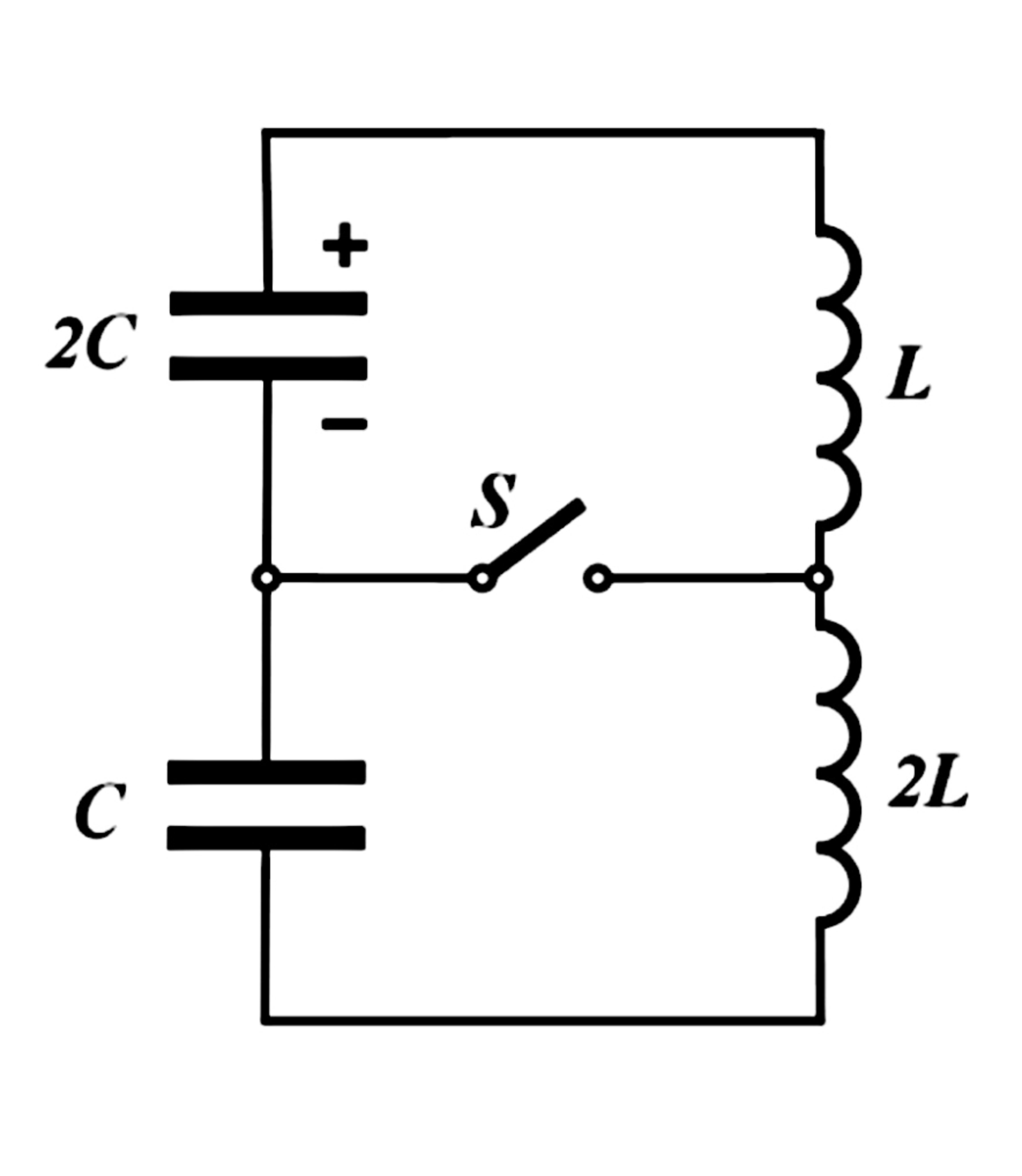
Inductor and Capacitor story
Initially, a switch
S
is unshorted in the circuit shown in the figure , a capacitor of capacitance
2
C
carries the electric charge
q
0
, a capacitor of capacitance
C
is uncharged, and there are no electric currents in both coils of inductance
L
and
2
L
, respectively. The capacitor starts to discharge and at the moment when the current in the coils reaches its maximum value, the switch
S
is instantly shorted. Find the maximum current
I
m
a
x
through the switch
S
thereafter.
 Answer comes in the form of
I
m
a
x
=
β
L
C
α
q
0
Answer comes in the form of
I
m
a
x
=
β
L
C
α
q
0
Type your answer as
α
+
β
=
?
The problem is not original.
The answer is 3.
This section requires Javascript.
You are seeing this because something didn't load right. We suggest you, (a) try
refreshing the page, (b) enabling javascript if it is disabled on your browser and,
finally, (c)
loading the
non-javascript version of this page
. We're sorry about the hassle.
2 solutions
@Steven Chase But I have not given data. Then how you solve that numerically??
Log in to reply
I picked L = C = 1 and q 0 = 1 0 . The answer at the very end obviously comes out to 2 1 0
Log in to reply
@Steven Chase
.Exactly Ha Ha. i know you very well. Before posting the question I know that you will do this only and also I know the value you will put in your code.
BTWSolving whole problem analytically is pure
F
U
N
.
BTW your solution is also nice. Thanks
@Steven Chase You are very smart person.
Log in to reply
Thanks. You are too. You're doing some very impressive things, especially given your relatively young age (if you don't mind my saying so)
Log in to reply
@Steven Chase Thanks. I didn't understand that “(if you don't mind my saying so) “ what does it mean?
Log in to reply
@A Former Brilliant Member – Some people get offended if you mention their age. So I was hoping you wouldn't be offended
Log in to reply
@Steven Chase – @Steven Chase But why some people get offended if you mention their age? . What is wrong with it???
Log in to reply
@A Former Brilliant Member – I don't think anything is really wrong with it. But it is something I have observed, nonetheless
@Steven Chase Are you posting any RLC problem or electromechanical problem., or you can post a problem of emf induced or Faraday law. I will be happy. I have seen your question of Paraboloid surface dynamics , at this time it's beyond my limit.
@Steven Chase Sie can you please continue the electro mechanics series. I think we should upgrade that problem by varying magnetic field and by replacing rod with a sinx curve upto ( 0 ≤ s i n x ≤ 2 π ) . Please i will happy if you post it today please
@Steven Chase sir can you help me in this problem by giving the solution by python code.
A cube(center is at origin) has a charge density per unit volume as
ρ
=
1
but the 1/4th part of cube is absent.
If you see the cube from
+
z
axis it will be like
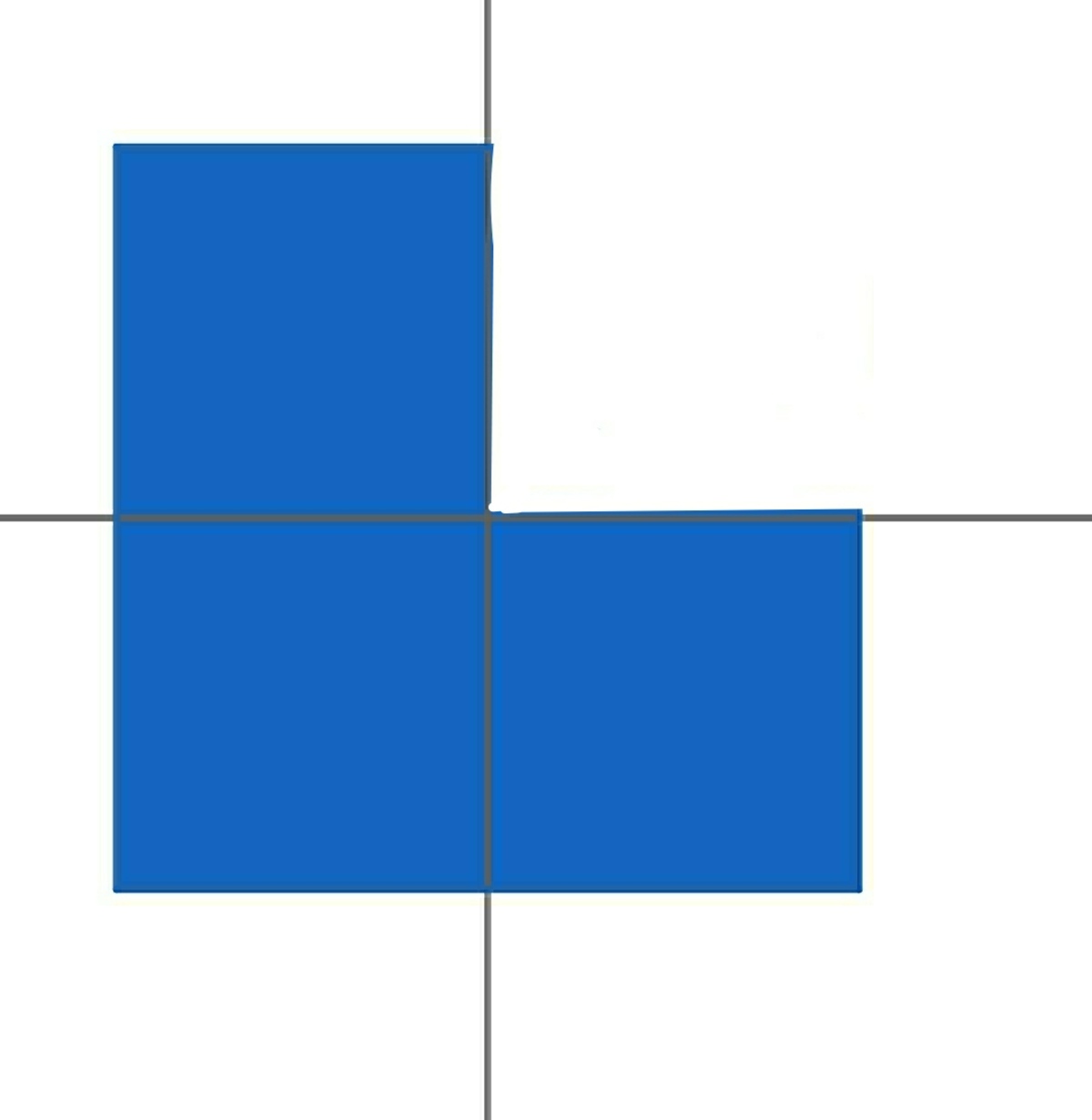 length of each side of cube is 1unit
Find the potential at
2
1
,
2
1
,
2
1
.
Thanks advance
length of each side of cube is 1unit
Find the potential at
2
1
,
2
1
,
2
1
.
Thanks advance
Log in to reply
Sure. Is ϵ 0 = 1 ?
Log in to reply
@Steven Chase yes
Log in to reply
@A Former Brilliant Member – I assume the missing portion corresponds to x > 0 , y > 0 . In that case, the potential comes out to ≈ 0 . 0 5 8 9
1 2 3 4 5 6 7 8 9 10 11 12 13 14 15 16 17 18 19 20 21 22 23 24 25 26 27 28 29 30 31 32 33 34 35 36 37 38 39 40 41 42 43 44 45 46 47 48 49 50 51 52 53 54 55 56 57 58 59 60 61 62 63 64 65 66 67 68 69 70 71 72 73 74 75 76 77 78 79 80 81 82 |
|
Log in to reply
@Steven Chase
–
@Steven Chase
Thankyou sir
I solved it analytically and verify my answer and my answer is correct.
Thank you
Log in to reply
@A Former Brilliant Member – Are you going to post that one?
@Steven Chase
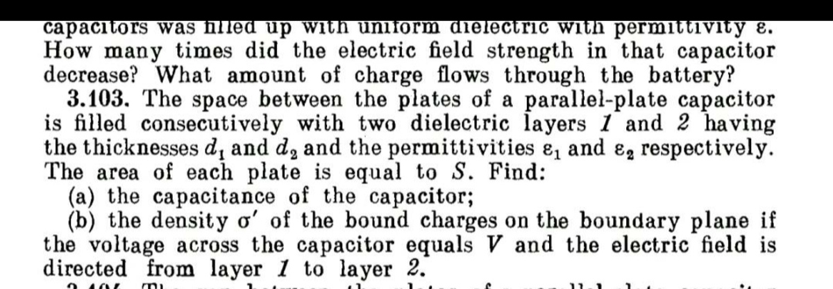
Sir can you help me in this problem 3.103 (b) part
BTW ,asking you doubts daily , did I disturb you??
Thanks in advance
Log in to reply
Assuming that ϵ 1 and ϵ 2 are the relative permittivity values, I get the following for the bound charge density. If this is correct, I can elaborate.
σ ′ = ϵ 0 ( d 1 ϵ 2 + d 2 ϵ 1 V ϵ 2 − V ϵ 1 )
And regarding the daily questions, I'm fine with them. Just be aware that I will not necessarily try to solve every one of them
Log in to reply
@Steven Chase
Thankyou so much sir.
Your answer is
C
o
r
r
e
c
t
!
Please explain all steps.
Thanks in advance.
Initial circuit equation :
3 L d t 2 d 2 q 1 + 2 C 3 q = 0 ⟹ d t 2 d 2 q 1 = − ω 2 q 1 . ( ω = 2 L C 1 ).
Substituting initial conditions, we get
q 1 = q 0 cos ( ω t ) , I m a x = ω q 0 .
Final circuit equation :
L d t 2 d 2 q 2 = − 2 C q 2 ⟹ d t 2 d 2 q 2 = − ω 2 q 2 .
Again, substituting initial conditions we get
q 2 = q 0 sin ( ω t ) ⟹ I f i n a l = ω q 0 cos ( ω t ) .
Hence the maximum final current is
ω q 0 = 2 L C q 0 .
So, α = 1 , β = 2 , α + β = 1 + 2 = 3 .
This was a fun problem. I solved numerically using two different circuits: one prior to switch closing (left of diagram) and one after switch closing (right of diagram). The differential equations are shown on each side. Prior to switch closing, the two inductors are lumped into one. The simulation is run for the first circuit until the time derivative of the inductor current becomes zero. At that point, currents I L 1 and I L 2 are initialized to the value of I L S , and the program switches over to the second circuit model and looks for the maximum switch current. This turns out to be 2 L C q 0 .