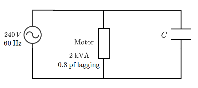
Motor Power Factor Correction

An ideal AC voltage source supplies an induction motor load in a residential application. How many microfarads ( μ F ) of capacitance should be connected in parallel with the motor in order to correct the load's overall power factor to unity?
Note: The source voltage magnitude is in RMS. "pf" stands for "power factor". The 2 kVA number is the apparent power drawn by the motor.
The answer is 55.26213.
This section requires Javascript.
You are seeing this because something didn't load right. We suggest you, (a) try
refreshing the page, (b) enabling javascript if it is disabled on your browser and,
finally, (c)
loading the
non-javascript version of this page
. We're sorry about the hassle.
1 solution
Here is an alternative solution using complex values, with j = − 1 :
Let us represent the motor with an impedance Z = R + j ω L (a resitor and inductor in series). The nominal power is S = ∣ U ∣ ∣ I ∣ = ∣ U ∣ 2 / ∣ Z ∣ , where ∣ U ∣ and ∣ I ∣ are effective values. The real power is P = ∣ U ∣ 2 / ∣ Z ∣ cos θ , where cos θ = R / ∣ Z ∣ = 0 . 8 is the power factor. With the numbers in the problem we get ∣ Z ∣ = ∣ S ∣ ∣ U ∣ 2 = 2 8 . 8 Ω and ω L = ∣ Z ∣ 1 − cos 2 θ = 1 7 . 3 Ω .
When the proper capacitor is in parallel with the motor the total impedance is purely ohmic, there is no imaginary part. The total impedance is ( 1 / Z + j ω C ) − 1 = ( R / ∣ Z ∣ 2 − j ω L / ∣ Z ∣ 2 + j ω C ) − 1 . This quantity is real if − j ω L / ∣ Z ∣ 2 + j ω C = 0 . Therefore ω C = ω L / ∣ Z ∣ 2 = 0 . 0 2 0 8 Ω − 1 We get C = 0 . 0 2 0 8 / 6 . 2 8 / 6 0 = 5 5 . 3 μ F .
Log in to reply
I'm thinking it would be fun to post a power factor correction problem for which this type of solution is necessary. In the revised problem, the source would have non-zero impedance, meaning that the addition of the capacitor changes the reactive power consumed by the load (unlike in this simple case). I would also no longer call the load a motor, but simply an RL branch (because motors are commonly considered to be "constant power" devices). Let me know if you would like to post one like that. Otherwise, I will.
Log in to reply
Please post it. BTW, I could not get the right solution to your original problem, because I used the 2kVA as the active power (P) and my result was a 0.8 factor off. Perhaps it would be helpful if you define the concepts of active and apparent powers for people not familiar with the terms.
Log in to reply
@Laszlo Mihaly – Ok, will do. I put a clarification in the problem as well.
@Laszlo Mihaly – The new problem is up now.
Log in to reply
@Steven Chase – I posted another version, from a different perspective
Log in to reply
@Laszlo Mihaly – Yeah, I'm eagerly awaiting it, once the figures are up
Log in to reply
@Steven Chase – It is complete, but the title is different from the earlier version (I deleted that because the numbers were not realistic).
Log in to reply
@Laszlo Mihaly – Nice one. Pretty dramatic effect
Apparent, active, and reactive power drawn by motor:
S = 2 0 0 0 P = 0 . 8 S = 1 6 0 0 Q = S 2 − P 2 = 1 2 0 0
Required capacitive reactance to offset Q:
Q = X V 2 X = Q V 2 = 1 2 0 0 2 4 0 2
Capacitance associated with reactance:
ω = 2 π f = 1 2 0 π X = ω C 1 C = ω X 1 = 1 2 0 π ( 2 4 0 2 ) 1 2 0 0 = 5 5 . 2 6 2 1 3 μ F