Op Amp Power Accounting

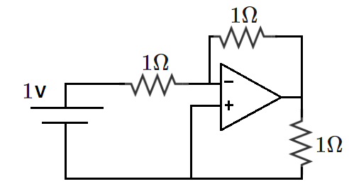
An inverting amplifier circuit is constructed using a single 1-volt DC battery, three 1 Ω resistors, and one operational amplifier (op amp), as shown above.
This particular op amp is ideal, which means that it has the following properties:
- The voltages at the ( + ) and ( − ) terminals are identical.
- The currents (into/out of) the ( + ) and ( − ) terminals are zero.
Given as a percentage, to one decimal place, how much of the total power consumed by the three resistors is supplied by the 1-volt battery?
Bonus: Where does the rest of the power come from? Why is it called an inverting amplifier?
The answer is 33.3.
This section requires Javascript.
You are seeing this because something didn't load right. We suggest you, (a) try
refreshing the page, (b) enabling javascript if it is disabled on your browser and,
finally, (c)
loading the
non-javascript version of this page
. We're sorry about the hassle.
2 solutions
@Steven Chase
what the hell, what is problem with you?????
You know what you have done with me????
I will not talk with you forever.
Log in to reply
What are you talking about?
Log in to reply
@Steven Chase you should know, what we are talking about. Leave it.
Log in to reply
@Talulah Riley – I actually have no idea what you are talking about
Log in to reply
@Steven Chase – @Steven Chase You should have idea, leave it.
@Steven Chase one thing which I want to say, you have done very very very wrong.
Log in to reply
What are you talking about?
Log in to reply
@Steven Chase
it is good to see I am getting an instant reply for my every comment, which I usually don't get.
Good to see you care,
I was just kidding you. Ha ha ha
Bye love you. :)
Let the potential of the bottom wire be 0 V .
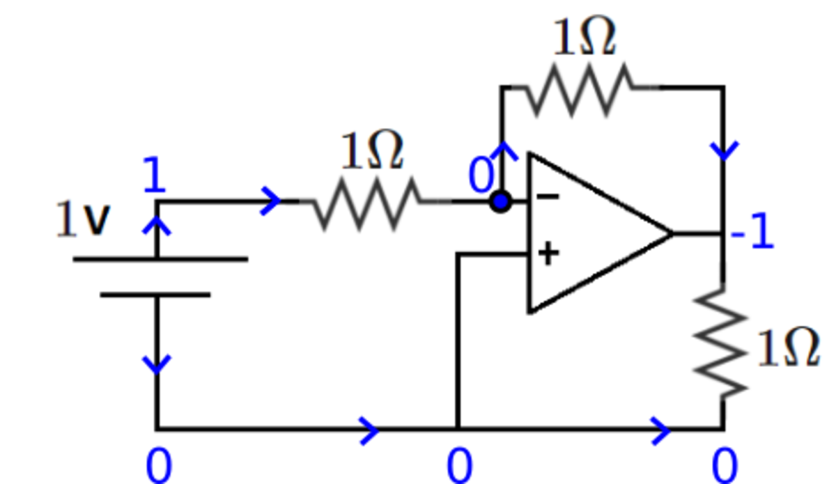
The point next to the ( − ) terminal is at the same potential, 0 V . we get the potential across the 1 Ω resistor is 1 V , and the current is 1 A towards right. Following this, we get the potential V o u t of the op amp as − 1 V .
The potentials and the direction of the current is shown in blue in the diagram below.

We see that potential difference across each resistor is 1 V , so current 1 A flows through each of the three resistors. The power dissipated by each resistor is I 2 R = 1 W . Out of this, only the top left resistor is powered by the battery. The other two resistors are powered by the op amp. Therefore the percentage of power supplied by the battery is 3 1 × 1 0 0 % = 3 3 . 3 % .
I was surprised to see that current is leaving the battery from both sides. Does this mean that the net charge on the battery changes with time?
Log in to reply
I think this paradox goes away when we include the op amp DC supply in the circuit. I'll attach a diagram showing this later.
Log in to reply
Thanks, your diagram makes it clear how the op amp's power source is connected and we can find the current flowing in the circuit correctly.
See the solution by @Pranshu Gaba for the majority of the analysis. However, the op amp is an active element with its own DC power source. When the DC power source for the op amp is not drawn, we seemingly run into a scenario in which the current flows out of both sides of the 1-volt battery simultaneously. This is resolved by including the op amp power source in the drawing, as shown below.