R-L-C oscillations, not L-C oscillations.
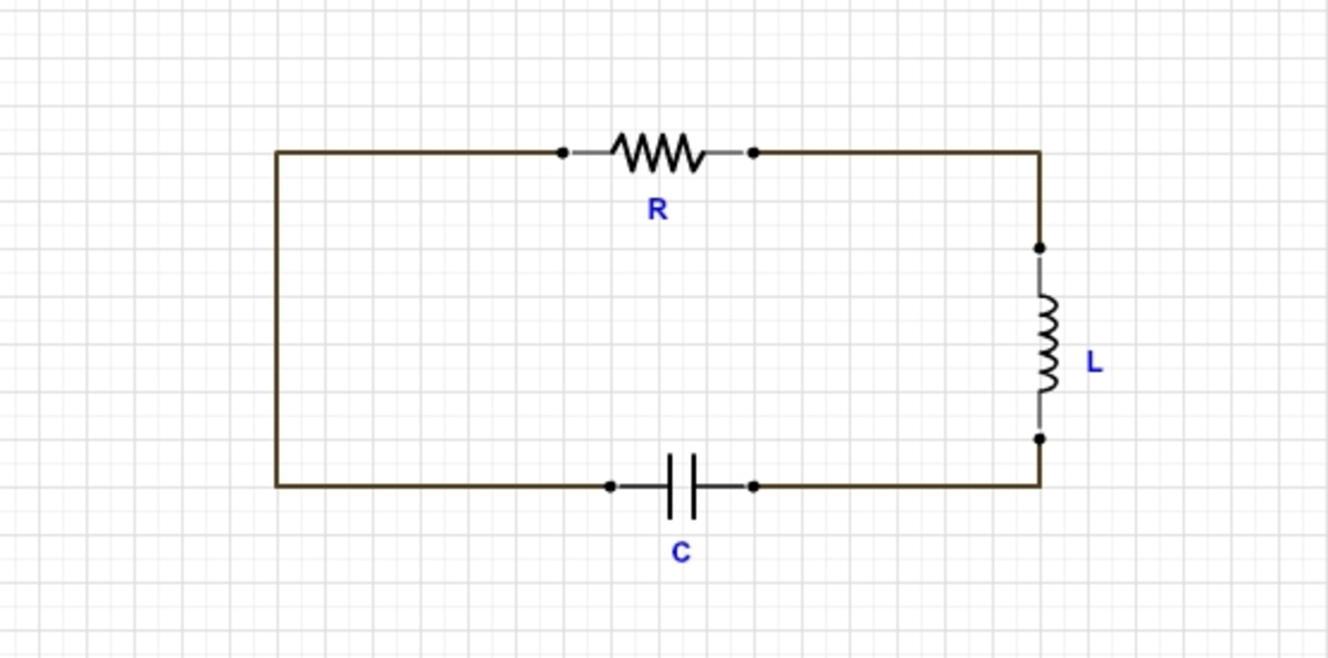
Consider a circuit that consists of an ideal inductor of inductance L , an ideal capacitor of capacitance C and a linear resistor of resistance R in series.
Let the capacitor be given an initial charge of q 0 and the circuit is left undisturbed to oscillate.
Find the ratio of the energy stored in the inductor due to the magnetic field to the energy stored in the capacitor due to the electric field at the instant when the current in the circuit is maximum.
Let that ratio be of the form of C β R γ ψ L α
Find ψ + α + β + γ .
The answer is 5.
This section requires Javascript.
You are seeing this because something didn't load right. We suggest you, (a) try
refreshing the page, (b) enabling javascript if it is disabled on your browser and,
finally, (c)
loading the
non-javascript version of this page
. We're sorry about the hassle.
3 solutions
Thanks for a short solution.
I was hoping someone would post this shorter way! Good job! (+1)! :)
Log in to reply
That night when you posted the question, I didn't see this solution and saved the question for later. I eventually forgot about it, but then saw it today and decided to solve it. :P
Consider the circuit as shown in the figure below:
In case of an ordinary L-C circuit, the oscillations are not restricted by anything, and so the angular velocity of the circuit stays at ω o = L C 1 , but in our case, since there is an external resistance attached, hence, there will be a loss of energy and so, the circuit would act as a damped oscillator.
Now, using the Kirchoff's voltage law , the sum of voltages across all the 3 components should be 0 . So,
C q + L d t d I + R I = 0
where q is the charge on the capacitor plates at any instant and I is the current through the circuit at any instant.
Now, substituting I = − d t d q , we get a differential equation in q that can be written as:
d t 2 d 2 q + d t d q L R − L C q = 0
The solution to this differential equation is identical to the solution of the differential equation for a damped SHM, which is:
q = q o e − δ t cos ω t
where δ = 2 L R and ω = ω o 2 − δ 2
After we have calculated the time dependence for q , we can get the same for the current I , by just differentiating the expression, which gives us:
I = q o e − δ t ( ω sin ω t + δ cos ω t )
Now, the question asks for the time at which I attains it's maximum value, which can be calculated by differentiating I and equating it to 0 .
d t d I = − q o e − δ t ( ( δ 2 − ω 2 ) cos ω t + ( 2 δ ω ) sin ω t ) = 0
Solving this, we get tan ω t = 2 δ ω ω 2 − δ 2 .
So, the question asks for the ratio of energy in the inductor at this instant to the ratio of energy in the capacitor at this instant, i.e.
E C E L = 2 C q 2 2 L I 2
Now, putting
- I = − q o e − δ t ( ω sin ω t + δ cos ω t )
- q = q o e − δ t cos ω t
- cos ω t = δ 2 + ω 2 2 δ ω
- sin ω t = δ 2 + ω 2 ω 2 − δ 2
and using the definitions of δ and ω , we get:
E C E L = C R 2 L
Phew! So, ψ = 1 , α = 1 , β = 1 and γ = 2 , giving us the answer as 5 .
....and we're done! :)
Excellent solution! Very clever
I see that the soln. uses the equation from a damped harmonic motion. However from the characteristic equation do we not get R^2C < 4L for the required form of the soln? Am I wrong ? If so can you please provide a coreection.
There is 1 thing I don't seem to understand, did you really have to go through all these steps to get the solution, I think it can be calculated directly
Log in to reply
Can you please specify what you mean by 'calculated directly'? I got the diff. equation and left the roots in the algebraic form for the manipulation work and ended up using vieta's theorem from the characteristic equation. I suppose thst is not what you are talking about though...?
Yea, it can be, from the first differential equation formed, but just to clear the basics of those who don't know such tricks, I decided to write the entire solution!
I don't know if it makes a difference, but the equation that I got was
L d t 2 d 2 q + R d t d q − C q = 0 .
Log in to reply
...and what logic did you use, exactly, to achieve a negative sign beside C q , but I don't think that should make a difference.
Log in to reply
In your diagram, let us take the left terminal of the capacitance as positive q , and by sign convention, i = d t d q denotes the current flowing from the left terminal to the right terminal ( i may be negative). It follows that
C q − R d t d q − L d t d i = 0 , hence the equation.
In fact, the differential equation that you have written is incorrect. Milind Blaze correctly pointed out that the equation should lead to a damped oscillation regardless of the values of C , R , L . While your logic that energy is being dissipated is correct, but it is not being reflected in the differential equation .
Log in to reply
@Shourya Pandey – It was just an assumption made by me with respect to the sign convention. If you say that the equation made by me is incorrect, that might not be wrong because instead of dealing with direction of current, I just picked up a general equation as the equation made by me and you will reflect also the same.
Log in to reply
@A Former Brilliant Member – But you used i = d t d q , right? For instance, if the left terminal of the capacitor were positive, and current flows from the right terminal to the left terminal, then i = − d t d q , not d t d q .
Log in to reply
@Shourya Pandey – Haha, that's what I'm saying, you are NOT wrong. It maybe true that I am wrong, but in the end, the solution is what matters. Look at this:
 This is for what I wrote
 This is what you say
Look at the sign convention, and solve the question. Trust me, you won't get a different answer. But, just to make it clearer for others, I'm going to edit my solution for what you're saying.
So if we consider the series connection,
V c + V r + V l = 0
V c + I R + L d t d I = 0
Now for maximum current,
d t d I = 0
So, V c + I R = 0
∴ V c = − I R
So ratio of energy,
R a t i o = 2 1 C V c 2 2 1 L I 2
= 2 1 C I 2 R 2 2 1 L I 2
= C R 2 L
So, Ans is 1 + 1 + 1 + 2 = 5
Let the charge on the capacitor at any instant be q, the current i.
Using Kirchoff's voltage law across the circuit we get,
L d t d i + i R + C q = 0
Let U L , U C be the magnetic energy stored in the inductor and electric energy in the capacitor respectively.
U L = 2 L i 2
U C = 2 C Q 2
U C U L = L C × ( q i ) 2
Coming back to the differential equation,
L d t d i + i R + C q = 0
When current is maximum, d t d i = 0
0 + i R = − c q
q i = − R C 1
∴ U C U L = L C × ( R C 1 ) 2 = R 2 C L
Comparing, α = β = ψ = 1 , γ = 2
α + β + γ + ψ = 5