RC circuit
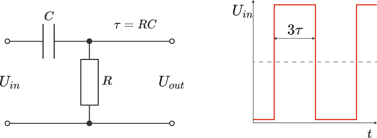
We send a square-wave signal as an input voltage U in ( t ) into an RC circuit and pick up the voltage at the resistor as an output signal U out ( t ) .
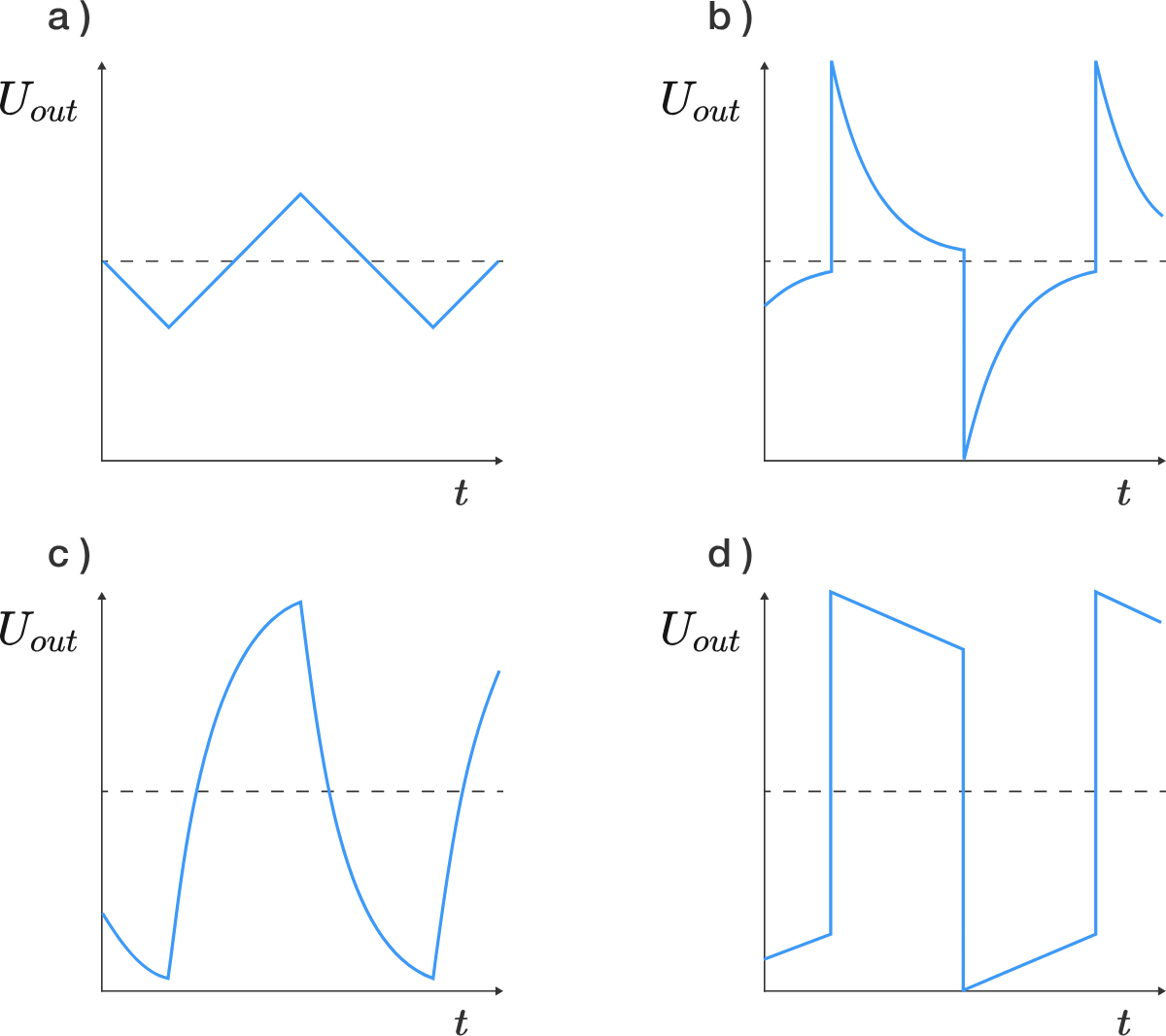
Which of the following is the shape of the output signal?
This section requires Javascript.
You are seeing this because something didn't load right. We suggest you, (a) try
refreshing the page, (b) enabling javascript if it is disabled on your browser and,
finally, (c)
loading the
non-javascript version of this page
. We're sorry about the hassle.
2 solutions
@Markus Michelmann @Steven Chase Shouldn't the voltage reverse its direction when the input voltage falls to zero? It will become a discharging circuit in which the current will flow in the reverse direction.
To me the graph between output voltage vs time should be like
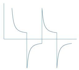
This is pretty much same as 'b' with the only difference that the dotted line is the time axis.
Log in to reply
In the existing diagrams, I interpret the dotted line as meaning "Uout = 0".
Log in to reply
Ahh, ok. What should be the peak value of the output voltage? Nearly 2 U i n , isn't it?
Log in to reply
@Rohit Gupta – Yes, that's right. Nearly twice the input voltage
The circuit shown is a high-pass filter that attenuates the low frequencies and acts as a differentiating element. This follows from the equations for the capacitor and the resistance: ⇒ C ( U in − U out ) U out = Q = R I = R d t d Q = τ d t d ( U in − U out ) with the time constant τ = R C . For a piecewise constant input signal U in , its derivative is zero almost everywhere, so that the differential equation is reduced to U out + τ d t d U out = 0 ⇒ U out = U 0 e − t / τ This exponential decay can be found in Figures b) and d). But the width of the square pulses is Δ t = 3 τ , so that the exponential function must have dropped to e − 3 ≈ 5 % at the end of the pulse, which corresponds to the image b).
A couple of simple observations:
1) The voltage across the capacitor cannot change discontinuously. Since the source voltage is equal to the capacitor voltage plus the resistor (output) voltage, if the source voltage changes discontinuously, the resistor (output) voltage must also. This means the answer is either (b) or (d).
2) In DC steady state, a capacitor is an open circuit (very high impedance). 5 time constants ( 5 τ ) is about the time it takes to get there. The source pulse width is ( 3 τ ) , which gets us close enough to DC steady state that the capacitor eats up nearly the entire source voltage before the polarity flips again, leaving almost nothing for the resistor. Choice (b) exhibits this behavior, but (d) does not. Hence, the answer is (b).