RLC 4-16-2020
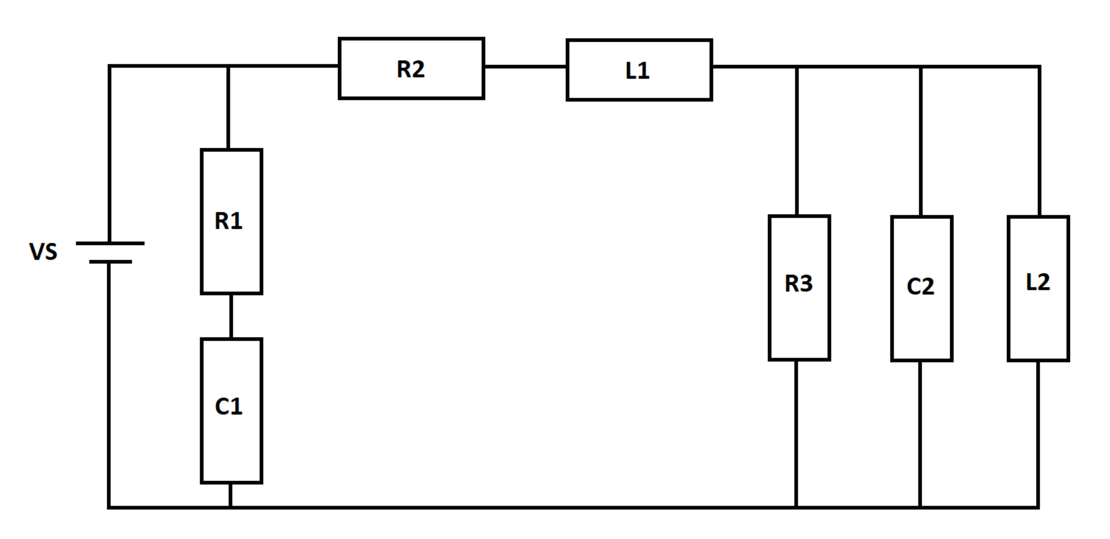
A DC voltage source excites an RLC network as shown below. At time t = 0 , the inductors and capacitors are de-energized.
I S is the current flowing out of the source. Let I S 0 be the source current at time t = 0 , and let I S ∞ be the limiting value of the source current as the elapsed time approaches infinity. Let I S m i n be the smallest source current value between t = 0 and t = ∞ .
Determine the following quantity:
Q = I S m i n I S 0 I S ∞
Details and Assumptions:
1)
V
S
=
1
0
2)
L
1
=
L
2
=
2
3)
C
1
=
C
2
=
1
4)
R
1
=
R
2
=
R
3
=
1
5)
All three currents are positive

The answer is 636.66.
This section requires Javascript.
You are seeing this because something didn't load right. We suggest you, (a) try
refreshing the page, (b) enabling javascript if it is disabled on your browser and,
finally, (c)
loading the
non-javascript version of this page
. We're sorry about the hassle.
1 solution
@Neeraj Anand Badgujar Here is my approach, for reference
Log in to reply
@Steven Chase Sir at step 21 it's written dt=10** (-6) . Does it mean that the phython had broked the time in such small time to calculate accurately?.
Log in to reply
Yes, usually I like to run the simulation with several different time steps spanning several orders of magnitude, to see that I get the same result with each value of the time step. For example, we can run with 1 0 − 4 , 1 0 − 5 , and 1 0 − 6 and see that the results are similar all three times.
Log in to reply
@Steven Chase – Thanks, Yes Sir I understand it fully. I upvoted it also .I was making a question but not able to solve. The question is that a charged particle ( q = 1 c ) is moving in the line z = 1 moving towards the + x axis with a speed 1 m s − 1 . A loop is placed at x 2 + y 2 = 1 and we can take loop's resistance as 1 Ω .Find the rate of current induced in the loop. How can we solve this ?? Please help.
Log in to reply
@A Former Brilliant Member – I found a nice resource for the magnetic field generated by a moving point charge. If you combine this with the integral form of Faraday's law, you should be able to solve for the voltage induced in the loop. That sounds like a fun problem.
https://www.pdx.edu/nanogroup/sites/www.pdx.edu.nanogroup/files/lecture 9 Magnetic Fields produced by a current ph 222 PRINT_9.pdf
Log in to reply
@Steven Chase – Thanks for sharing link. Yes it's a fun problem but it will require hard calculus I think. What specification did this link have in physics?
Log in to reply
@A Former Brilliant Member – What do you mean by specification? Do you plan to post the problem?
Log in to reply
@Steven Chase – @Steven Chase Sir I have planned but I think I can't solve it. So was just telling you the problem. So that you can make or post the problem.
@Steven Chase – @Steven Chase Sir according to you which is best udemy, coursera, or edx??
Log in to reply
@A Former Brilliant Member – I'm not familiar with any of those, actually
Log in to reply
@Steven Chase – @Steven Chase that flux problem which you posted of multi coloured it was very easy. Can you increase the difficulty?
@Steven Chase – @Steven Chase Sorry if you feel any inconvenience.
@Steven Chase Sir are you planning to post that question of charge moving in + x direction with a changing flux in the ring. I am planning but can't able to solve. So you can make and post question. It would be very interesting.
Log in to reply
How about this? Instead of calculating the induced voltage in the loop, why don't you post a problem that asks to find the magnetic flux in the loop at a particular time, due to a moving point charge? That problem is considerably easier, and it is still interesting
Log in to reply
@Steven Chase – @Steven Chase Ok Sir i am posting.
The state variables are the inductor currents and the capacitor voltages. Derive expressions for the time derivatives of the state variables in terms of the state variables and the forcing function.
Basic equations:
V L 1 = L 1 I ˙ L 1 V L 2 = L 2 I ˙ L 2 I C 1 = C 1 V ˙ C 1 I C 2 = C 2 V ˙ C 2
Re-writing the left-hand sides in terms of state variables and the source voltage:
V S − R 2 I L 1 − V C 2 = L 1 I ˙ L 1 V C 2 = L 2 I ˙ L 2 R 1 V S − V C 1 = C 1 V ˙ C 1 I L 1 − I L 2 − R 3 V C 2 = C 2 V ˙ C 2
And the source current is:
I S = I C 1 + I L 1 = R 1 V S − V C 1 + I L 1
Then we numerically integrate, as usual. By inspection, the currents at t = 0 and t = ∞ are 1 0 . The minimum current is ≈ 6 . 3 6 6 . Simulation code is attached.