Transformer (8-12-2020)
A transformer is governed by the following equations:
E 1 = Z S I 1 + Z M I 2 E 2 = Z M I 1 + Z S I 2
In the equations, E 1 and E 2 are the terminal voltages and I 1 and I 2 are the terminal currents (note the polarity conventions in the diagram). Z S and Z M are the transformer winding self and mutual impedances.
An AC voltage source with internal voltage E S and internal impedance Z 1 is connected across the first set of terminals, and an impedance Z 2 is connected across the second set of terminals. Let Z 2 be purely resistive ( Z 2 = R + j 0 ) .
What is the limiting value of the magnitude of I 1 as R approaches infinity?
Bonus: This result is a bit surprising. What conclusion can be drawn?
Details and Assumptions:
1)
E
S
=
1
0
+
j
0
2)
Z
1
=
2
+
j
5
3)
Z
S
=
0
+
j
1
0
4)
Z
M
=
0
+
j
5
5)
Consider all quantities to be complex numbers. The quantity
j
is the imaginary unit
![]()
The answer is 0.6608.
This section requires Javascript.
You are seeing this because something didn't load right. We suggest you, (a) try
refreshing the page, (b) enabling javascript if it is disabled on your browser and,
finally, (c)
loading the
non-javascript version of this page
. We're sorry about the hassle.
2 solutions
Is it posted now??
I just posted it
@Steven Chase
in your new problem the concept will be of Moment of Inertia only??
That
M
R
2
or it is a different type of moment of inertia?
Like in my knowledge the moment of inertia of Disc is
2
M
r
2
about perpendicular to it's plane and passing through original.
Are you asking about this type of. Moment of inertia only????
Please reply.
@Steven Chase
sir do you have any idea that how Brilliant decide level of a particular problem.
I think they have 5 cheats of paper folded, and inside ever consecutive cheat 1,2,3,4,5 level are written.
After that they throw them in air and one selected cheat will be the level of problem.
Your new problem has got level 2 and i think in my opinion the most toughest problem of flux in whole world is my Complex flux, which has also got level 2
Log in to reply
From what I have observed, it is based on the initial rating you give the problem, as well as the percentage of people who solve it correctly.
@Steven Chase
can you use python code to solve this one
Thanks in advance
Hope I am not disturbing you.
Log in to reply
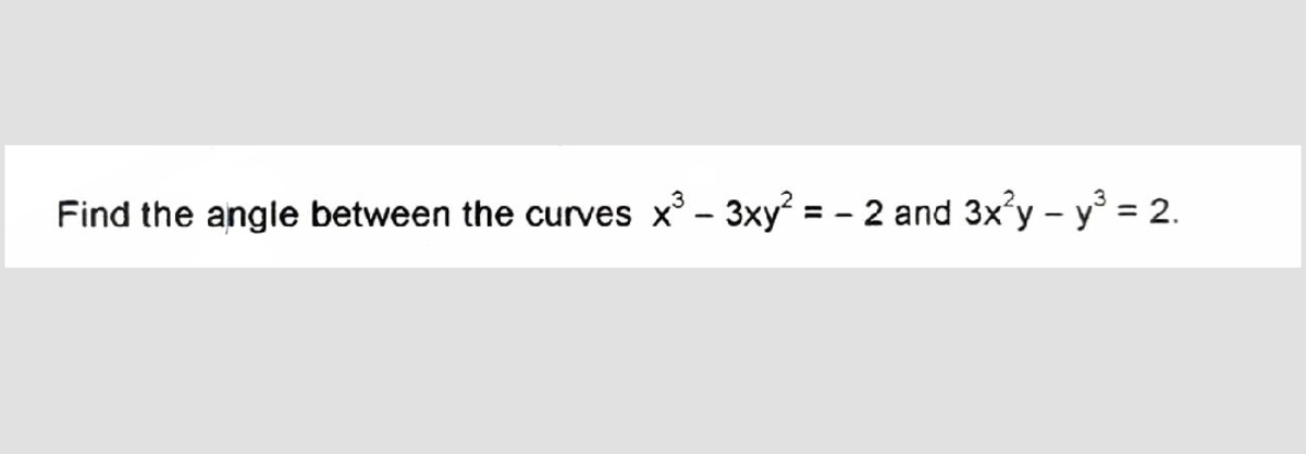
Why do you want code for this? It is easy to show by hand that the slope of one curve is the negative reciprocal of the slope of the other curve. The curves therefore make a 90 degree angle where they intersect.
Log in to reply
@Steven Chase it is in this question only.
Sometimes the curve doesn't make 90 degree.and it also becomes large while evaluating with pen.
By using python code can we find?
Log in to reply
@Talulah Riley – If you derive the d x d y expressions for both curves, you will find that the product of the two is negative one. This means that at any point of intersection, the curves are at a right angle.
Log in to reply
@Steven Chase – @Steven Chase Thank you so much sir, Thanks, it means a lot. Thanks
@Steven Chase
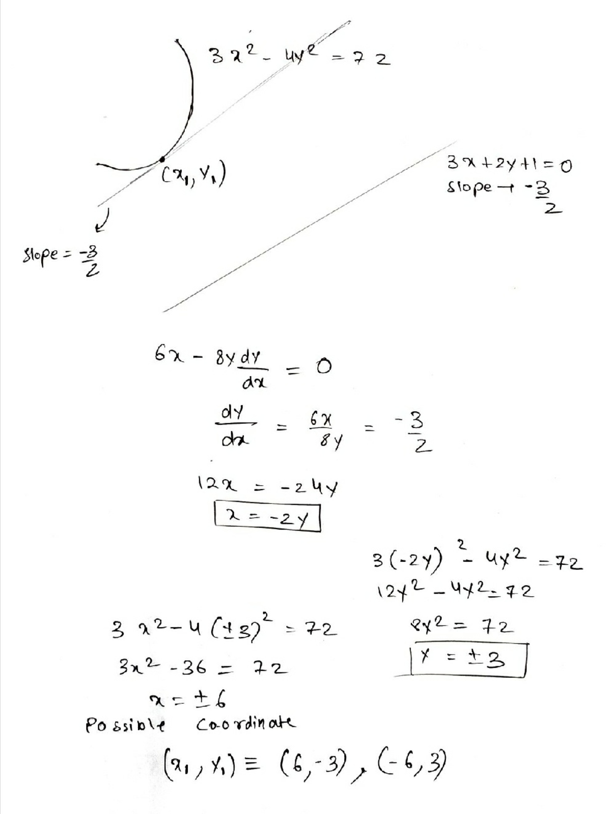
can you help me in this problem, by solving it anaylitically
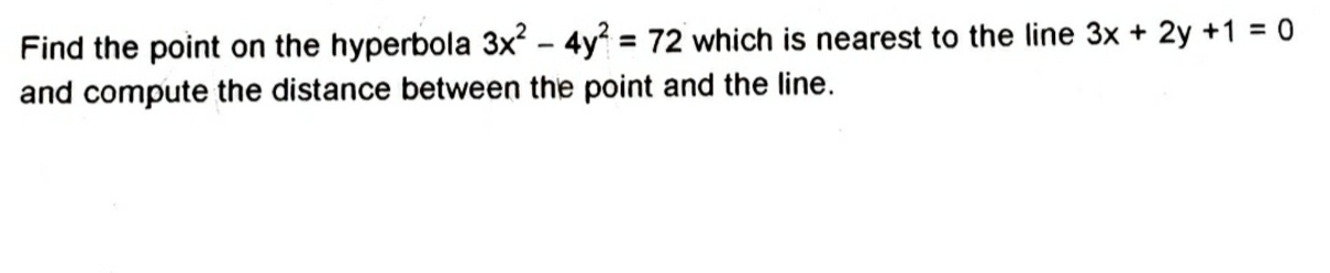
Thanks in advance
Hope I am not disturbing you.
Log in to reply
This one is fairly easy to do with code and hard to do by hand.
@Steven Chase so are you trying this question or not??
Log in to reply
Probably not by hand
Log in to reply
@Steven Chase
finally i solved it. Hope this will help you too

@Steven Chase
sir Why Brilliant is not again adding that feature of how many people have solved the problem till now on such a big demand.
Can we do something more.
Anyhow I want to see that feature as fast as possible?
Can you do something?
.
Log in to reply
I doubt that it will get fixed. They probably just tried to remove the feature and didn't remove it completely.
Nice problem.
I think the surprising results which can be drawn is at a particular value of
I
1
, the
Z
2
will behave like a
∞
resistance.
Am I correct?? Please correct me if I am wrong :)
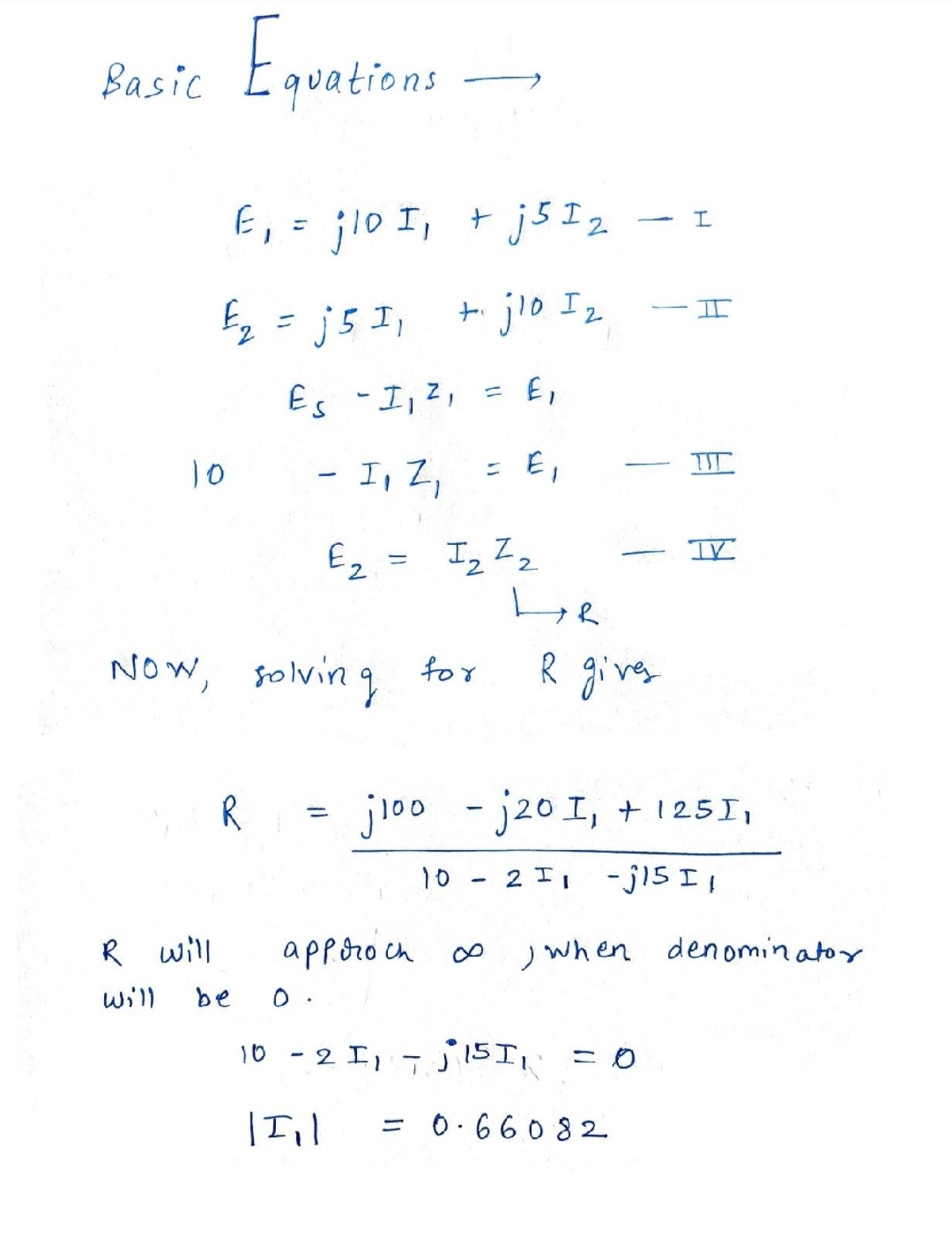
@Lil Doug has given a clever solution centered around representing the load resistance in terms of the other quantities. I will approach it in a more conventional way, and elaborate on the bonus.
Expand the left sides of the equations in terms of other quantities.
E 1 = E S − Z 1 I 1 = Z S I 1 + Z M I 2 E 2 = − Z 2 I 2 = Z M I 1 + Z S I 2
Simplify:
E S = ( Z S + Z 1 ) I 1 + Z M I 2 0 = Z M I 1 + ( Z S + Z 2 ) I 2
From this point, one can readily solve for the currents. Take the limit of ∣ I 1 ∣ as the magnitude of Z 2 goes to infinity. If the transformer were ideal (just a ratio changer for voltage and current), we would expect both I 1 and I 2 to go to zero as the load impedance increases. This does not happen, which indicates that the mathematics does not describe an ideal transformer.
Instead, it describes a more realistic representation of a transformer which contains series impedances called "leakage impedances", as well as a shunt impedance called a "magnetizing impedance". In the diagram below, the non-ideal transformer on the left can be represented (on the right) as an ideal transformer connected to these leakage and magnetizing impedances. The leakage and magnetizing impedance values can be expressed in terms of Z S and Z M .
In this problem, when the load impedance becomes infinite, current I 1 can still flow through the magnetizing impedance. The current measured in the "no load" (infinite load impedance) condition is known as the "magnetizing current".